EVAL_PAN4555 Panasonic - ECG, EVAL_PAN4555 Datasheet - Page 11
EVAL_PAN4555
Manufacturer Part Number
EVAL_PAN4555
Description
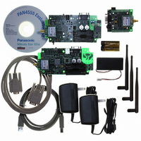
ZIGBEE DEVELOPMENT KIT PAN4555
Manufacturer
Panasonic - ECG
Series
PAN4555r
Type
Zigbeer
Datasheets
1.EVAL_PAN4555ETU.pdf
(16 pages)
2.EVAL_PAN4555.pdf
(30 pages)
3.EVAL_PAN4555.pdf
(2 pages)
Specifications of EVAL_PAN4555
Frequency
2.4GHz
For Use With/related Products
PAN4555
Lead Free Status / RoHS Status
Lead free / RoHS Compliant
Other names
EVAL_PAN4555
P14157
Q3510557
P14157
Q3510557


CLASSIFICATION
Einstufung
SUBJECT
Thema
CUSTOMER’S CODE
EvalPAN4555
9.2.
Panasonic Electronic Devices (EUROPE) GmbH
RF TESTING OF PAN4555
refer also to: freescale\documentation\13213EVKUG.pdf on the CD
ZigBee radio testing can be done using the “Test Tool” on a PC. Operation and some often
used functions are described below:
European Technology Center
1. Install TestTool (from folder 132xxEVKCD on CD) on a PC with a free COM port.
2. Set the Testboard COM port to UART1 and connect it to the PC
3. If needed (for example for PER measurements within ZigBee Radio Test
4. This step is only required for reprogramming:
5. Push RESET on the testboard and open TestTool\View\ZigBee Radio Test.
6. Open TestTool
7. Important: In section “SPI Registers” read modem control_b register address x07,
8. RF Testing Tx mode
9. RF Testing Rx mode
“ Set Continuous TX” with the result “Succeeded”. PAN4555 is set to a continuous
a USB to COM converter cable could help.
of TestTool) connect the second Testboard (set to UART1 too) to a second
free COM port of the PC. If your PC does not provide enough serial ports,
Flash program the embedded_bootloader_4555.s19 via the BDM and upload the
EVK_PTC_Demo_w_Embedded_Bootloader_V202_13213_NCB via the serial cable to
PAN4555 as described in 8.1.
the result is 0x4ca0. This content means dual port mode as for 13213-NCB devices.
Change this setting by writing 0x5ca0 to register x07, enabling the MC13214 internal
Rx/Tx switch for single port operation.
Remark: in case of missing rf input/output while testing with TestTool readout this
register in order to check if it is still set to 0x5ca0 .
- “Channel”, write for example 0x0b for the lowest frequency at 2405MHz or
- “Xtal Trim”, the readout value is 0x7e. For series production this value might be
- “Spi Register 12”
The most important parameter for Rx mode is the sensitivity determined by
increasing the path loss between transmitter and receiver until the Packet Error Rate
inrceases from 0 to 1% (with 20 bytes payload according to the IEEE802.15.4
requirements). For detailed information on how to run PER measurements refer to
the freescale documentation.
Remark: Make shure that both Transmitter and Receiver are set to single
port mode as described under point 7.
output power or carrier frequency accuracy.
The related settings are:
unmodulated carrier for testing of wanted and unwanted (e.g. harmonics)
0x1a for the highest frequency at 2480MHz.
adjusted for PAN4555
The default readout 0xbc sets PAN4555 to a power of approximately –3dBm.
In order to check the harmonics power, write 0xff for maximum power of
approximately +1dBm at the carrier frequency.
TM
EvalBoard PAN4555
and Push “PING” and “HOOK” for a device firmware test.
PANASONIC’S CODE
PRELIMINARY
APPROVED
genehmigt
No.
DS-Eval4555-2400
PAGE
Seite
DATE
Datum
CHECKED
geprüft
30.03.2007
11 of 16
DESIGNED
Erstellt
REV.
01
Related parts for EVAL_PAN4555
Image
Part Number
Description
Manufacturer
Datasheet
Request
R


Part Number:
Description:
MICROPHONE OMNI 6X2.2MM W/CAP
Manufacturer:
Panasonic - ECG
Datasheet:

Part Number:
Description:
CAP .0018UF 16V PPS FILM 0603 5%
Manufacturer:
Panasonic - ECG

Part Number:
Description:
CAP .01UF 100V PEN FILM 1210 5%
Manufacturer:
Panasonic - ECG
Datasheet:

Part Number:
Description:
CAP .1F 5.5V GOLD SD VERTICAL
Manufacturer:
Panasonic - ECG
Datasheet:

Part Number:
Description:
SUR ABSORBER 14MM 39V 1000A ZNR
Manufacturer:
Panasonic - ECG
Datasheet:

Part Number:
Description:
FILTER LINE 23.3MH 2A
Manufacturer:
Panasonic - ECG
Datasheet:

Part Number:
Description:
BEAD CORE 600 OHM 100MA 0603 SMD
Manufacturer:
Panasonic - ECG
Datasheet:

Part Number:
Description:
SAW FILTER PCS 1960 MHZ 50/150
Manufacturer:
Panasonic - ECG
Datasheet:
Part Number:
Description:
SAW FILTER WCDMA 1950 MHZ 50/50
Manufacturer:
Panasonic - ECG
Datasheet:
Part Number:
Description:
SAW FILTER EGSM 942 MHZ 50/150
Manufacturer:
Panasonic - ECG
Datasheet:
Part Number:
Description:
SAW FILTER DCS 1842 MHZ 50/150
Manufacturer:
Panasonic - ECG
Datasheet:
Part Number:
Description:
POT 1.0M OHM 3MM SEALED SMD 3 TT
Manufacturer:
Panasonic - ECG
Datasheet:

Part Number:
Description:
MODULE POWER DC/DC 48V/28V 600W
Manufacturer:
Panasonic - ECG
Datasheet:
Part Number:
Description:
RES ARRAY 22 OHM 5% 4 RES SMD
Manufacturer:
Panasonic - ECG
Datasheet: