ATAVRRZ201 Atmel, ATAVRRZ201 Datasheet - Page 15
ATAVRRZ201
Manufacturer Part Number
ATAVRRZ201
Description
KIT RZ201 CTLR BOARDS & SOFTWARE
Manufacturer
Atmel
Series
AVR®r
Type
802.15.4/Zigbeer
Specifications of ATAVRRZ201
Frequency
2.4GHz
Wireless Frequency
2.4 GHz
Interface Type
JTAG
Antenna
PCB Trace
Silicon Manufacturer
Atmel
Silicon Core Number
ATmega1281V, AT86RF230
Kit Application Type
Wireless Connectivity
Application Sub Type
ZigBee Wireless Network
Silicon Family Name
ZigBee
Rohs Compliant
Yes
For Use With/related Products
AT86RF230
Lead Free Status / RoHS Status
Lead free / RoHS Compliant


5.1
Demonstration Kit User Guide
Starting the
network
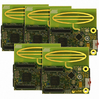
The Demonstration Kit consists of five RCB nodes, one of which is connected into the
Display Board and will act as a PAN Coordinator. Starting the network and experiment-
ing with network reconfiguration are discussed in the following subparagraphs.
Note:
After the RCB is connected to the Display Board, the power switch on the Display Board
should be moved to BAT for battery power, or EXT for AC Adaptor power. The Atmel
splash screen is displayed on the LCD display similar to that shown in Figure 5-1.
Figure 5-1. Atmel splash screen
Note:
While the splash screen is displayed, move the power switch on the attached RCB to
ON (towards the LCD screen). The RCB will then scan all channels in the 2450 MHz
band - Channels 11 (2405 MHz) through 26 (2480 MHz) for other active PANs. The dis-
play during channel scan is shown in Figure 5-2.
Figure 5-2. Screen during Channel scan
The RCB firmware will determine if a PAN exists on each channel and select the lowest
channel where there is no conflicting PAN. When a channel is selected (11 in this case),
the display will be similar to Figure 5-3.
The following paragraph discusses starting the network with the PAN Coordina-
tor started first and then the nodes coming online in random sequence. The
network can also be started with the nodes being started first and then the PAN
Coordinator coming online and establishing the network. A combination of
these two approaches can also be used.
While the Display Board can be powered from an ac adaptor or batteries, all of
the RCBs must have batteries installed.
Section 5 Running the
Demonstration
5183A–ZIGB–12/07/06
5-1
Related parts for ATAVRRZ201
Image
Part Number
Description
Manufacturer
Datasheet
Request
R

Part Number:
Description:
DEV KIT FOR AVR/AVR32
Manufacturer:
Atmel
Datasheet:

Part Number:
Description:
INTERVAL AND WIPE/WASH WIPER CONTROL IC WITH DELAY
Manufacturer:
ATMEL Corporation
Datasheet:
Part Number:
Description:
Low-Voltage Voice-Switched IC for Hands-Free Operation
Manufacturer:
ATMEL Corporation
Datasheet:
Part Number:
Description:
MONOLITHIC INTEGRATED FEATUREPHONE CIRCUIT
Manufacturer:
ATMEL Corporation
Datasheet:
Part Number:
Description:
AM-FM Receiver IC U4255BM-M
Manufacturer:
ATMEL Corporation
Datasheet:
Part Number:
Description:
Monolithic Integrated Feature Phone Circuit
Manufacturer:
ATMEL Corporation
Datasheet:
Part Number:
Description:
Multistandard Video-IF and Quasi Parallel Sound Processing
Manufacturer:
ATMEL Corporation
Datasheet:
Part Number:
Description:
High-performance EE PLD
Manufacturer:
ATMEL Corporation
Datasheet:
Part Number:
Description:
8-bit Flash Microcontroller
Manufacturer:
ATMEL Corporation
Datasheet:
Part Number:
Description:
2-Wire Serial EEPROM
Manufacturer:
ATMEL Corporation
Datasheet: