101-1262 Rabbit Semiconductor, 101-1262 Datasheet
101-1262
Specifications of 101-1262
316-1138


Related parts for 101-1262


101-1262 Summary of contents
Page 1
RabbitCore RCM5400W C-Programmable Wi-Fi Core Module OEM User’s Manual 019–0169 • 090430–B ...
Page 2
... Rabbit, RabbitCore, and Dynamic C are registered trademarks of Digi International Inc. Wi- registered trademark of the Wi-Fi Alliance. Rabbit 5000 is a trademark of Digi International Inc. The latest revision of this manual is available on the Rabbit Web site, www.rabbit.com, for free, unregistered download. Rabbit Semiconductor Inc. Trademarks www.rabbit.com RabbitCore RCM5400W ...
Page 3
Chapter 1. Introduction 1.1 RCM5400W/RCM5450W Features .....................................................................................................2 1.2 Advantages of the RCM5400W............................................................................................................3 1.3 Development and Evaluation Tools......................................................................................................4 1.3.1 RCM5400W Development Kit .....................................................................................................4 1.3.2 Software ........................................................................................................................................5 1.3.3 Online Documentation ..................................................................................................................5 1.4 Certifications.........................................................................................................................................6 1.4.1 FCC Part 15 Class B .....................................................................................................................6 1.4.2 Industry ...
Page 4
Memory .............................................................................................................................................. 45 4.6.1 SRAM......................................................................................................................................... 45 4.6.2 Flash Memory............................................................................................................................. 45 4.6.3 Serial Flash ................................................................................................................................. 45 Chapter 5. Software Reference 5.1 More About Dynamic C ..................................................................................................................... 47 5.2 Dynamic C Function Calls ................................................................................................................ 49 5.2.1 Digital I/O................................................................................................................................... 49 5.2.2 Serial ...
Page 5
B.3 Power Supply .....................................................................................................................................96 B.4 Using the Prototyping Board..............................................................................................................97 B.4.1 Adding Other Components.........................................................................................................99 B.4.2 Measuring Current Draw............................................................................................................99 B.4.3 Analog Features........................................................................................................................100 B.4.4 Serial Communication ..............................................................................................................100 B.4.4.1 RS-232 ............................................................................................................................. 100 B.5 Prototyping Board Jumper Configurations ......................................................................................102 Appendix C. Power Supply C.1 Power ...
Page 6
RabbitCore RCM5400W ...
Page 7
The RCM5400W RabbitCore modules use the Wi-Fi/802.11b/g functionality of the Rabbit create a low-cost, low-power, embedded wireless control and communications solution for your embedded control system. The Rabbit ® 5000 microprocessor features include hardware DMA, clock speeds ...
Page 8
RCM5400W/RCM5450W Features • Small size: 1.84" × 2.85" × 0.55" (47 mm × × 14 mm) • Microprocessor: Rabbit 5000 running at 73.73 MHz • general-purpose I/O lines configurable with up to four alternate ...
Page 9
The RCM5400W series is programmed over a standard PC USB port through a program- ming cable supplied with the Development Kit. The RCM5400W may also be pro- grammed remotely using the Remote Program Update library with Dynamic C v. 10.54 ...
Page 10
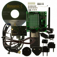
Development and Evaluation Tools 1.3.1 RCM5400W Development Kit The RCM5400W Development Kit contains the hardware essentials you will need to use the RCM5400W module. The items in the Development Kit and their use are as follows. • RCM5400W module ...
Page 11
Software The RCM5400W is programmed using version 10.50 or later of Dynamic C. A compatible version is included on the Development Kit CD-ROM. This version of Dynamic C includes the popular µC/OS-II real-time operating system, point-to-point protocol (PPP), FAT ...
Page 12
Certifications The systems integrator and the end-user are ultimately responsible for the channel range and power limits complying with the regulatory requirements of the country where the end device will be used. Dynamic C function calls and sample programs ...
Page 13
Labeling Requirements (FCC 15.19) FCC ID: VCB-E59C4472 This device complies with Part 15 of FCC rules. Operation is subject to the following two conditions: (1) this device may not cause harmful interference, and (2) this device must accept any interference ...
Page 14
Europe The marking shall include as a minimum: • the name of the manufacturer or his trademark; • the type designation; • equipment classification, (see below). Receiver Class Highly reliable SRD communication media, e.g., serving human life 1 inherent ...
Page 15
... Install Dynamic C To develop and debug programs for the RCM5400W series of modules (and for all other Rabbit Semiconductor hardware), you must install and use Dynamic C. If you have not yet installed Dynamic C version 10.50 (or a later version now by inserting the Dynamic C CD from the Development Kit in your PC’s CD-ROM drive. If autorun is enabled, the CD installation will begin automatically ...
Page 16
Hardware Connections There are three steps to connecting the Prototyping Board for use with Dynamic C and the sample programs: 1. Prepare the Prototyping Board for Development. 2. Attach the antenna to the RCM5400W module. 3. Attach the RCM5400W ...
Page 17
Step 2 — Attach the Antenna to the RCM5400W Module Attach the antenna to the antenna SMA connector on the RCM5400W as shown in Figure 3. Figure 3. Attach the Antenna to the RCM5400W Module CAUTION: Do not remove ...
Page 18
Step 3 — Attach Module to Prototyping Board Turn the RCM5400W module so that the mounting holes line up with the corresponding holes on the Prototyping Board. Insert the metal standoffs as shown in Figure 4, secure them from ...
Page 19
Step 4 — Connect Programming Cable The programming cable connects the module to the PC running Dynamic C to download programs and to monitor the module during debugging. Connect the 10-pin connector of the programming cable labeled the RCM5400W ...
Page 20
Step 5 — Connect Power Once all the other connections have been made, you can connect power to the Prototyping Board. If you have the universal AC adapter, prepare the AC adapter for the country where it will be ...
Page 21
Run a Sample Program If you already have Dynamic C installed, you are now ready to test your programming connections by running a sample program. Start Dynamic C by double-clicking on the Dynamic C icon on your desktop or ...
Page 22
Troubleshooting If you receive the message Could Not Open Serial Port assigned to the USB programming cable was identified and set up in Dynamic C as described in the preceding section. If you receive the message No Rabbit Processor ...
Page 23
Where From Here? If the sample program ran fine, you are now ready the sample programs in Chapter 3 and to develop your own applications. The sample programs can be easily mod- ...
Page 24
RabbitCore RCM5400W ...
Page 25
R To develop and debug programs for the RCM5400W (and for all other Rabbit hardware), you must install and use Dynamic C. This chapter provides a tour of its major features with respect to the RCM5400W modules. 3.1 Introduction ...
Page 26
Sample Programs Of the many sample programs included with Dynamic C, several are specific to the RCM5400W modules. These programs will be found in the —Demonstrates use of the digital outputs by having you turn LEDs • CONTROLLED.C DS2 ...
Page 27
TAMPERDETECTION.C mode. When an attempt is detected, the battery-backed onchip-encryption RAM on the Rabbit 5000 is erased. This battery-backed onchip-encryption RAM can be useful to store data such as ...
Page 28
Use of Serial Flash The following sample programs can be found in the SAMPLES\RCM5400W\Serial_Flash folder. —This program runs a simple Web server and stores a log of • SERIAL_FLASHLOG.C hits on the home page of the serial flash “server.” ...
Page 29
Serial Communication The following sample programs are found in the —This program demonstrates how to configure Serial Port D for • FLOWCONTROL.C CTS/RTS flow control with serial data coming from Serial Port C (TxC) at 115,200 bps. The serial ...
Page 30
RS-232 serial • SIMPLE3WIRE.C communication. Lower case characters are sent on TxC, and are received by RxD. The received characters are converted to upper case and are sent out on TxD, are received on RxC, and ...
Page 31
Real-Time Clock If you plan to use the real-time clock functionality in your application, you will need to set the real-time clock. Use the SETRTCKB.C folder, and follow the onscreen prompts. The SAMPLES\RTCLOCK program in the Dynamic C SAMPLES\RTCLOCK ...
Page 32
RabbitCore RCM5400W ...
Page 33
Chapter 4 describes the hardware components and principal hardware subsystems of the RCM5400W. Appendix A, “RCM5400W Specifica- tions,” provides complete physical and electrical specifications. Figure 6 shows the Rabbit-based subsystems designed into the RCM5400W. Figure 6. RCM5400W Subsystems The 73.73 ...
Page 34
RCM5400W Digital Inputs and Outputs Figure 7 shows the RCM5400W pinouts for header J1. standard 2 × 25 IDC header with a nominal 1.27 mm pitch. Headers Figure 7. RCM5400W Pinout RabbitCore RCM5400W ...
Page 35
Figure 8 shows the use of the Rabbit 5000 microprocessor ports in the RCM5400W modules. Figure 8. Use of Rabbit 5000 Ports The ports on the Rabbit 5000 microprocessor used in the RCM5400W are configurable, and so the factory defaults ...
Page 36
Table 2. RCM5400W Pinout Configurations Pin Pin Name 1 VIN 2 GND 3 /RES_OUT Reset output 4 /IORD Output 5 /IOWR Output 6 /RESET_IN Input 7 VBAT_EXT Battery input 8–15 PA[0:7] Input/Output 16 PB0 Input/Output 17 PB1 Input/Output 18 PB2 ...
Page 37
Table 2. RCM5400W Pinout Configurations (continued) Pin Pin Name 24 PC0 Input/Output 25 PC1 Input/Output 26 PC2 Input/Output 27 PC3 Input/Output 28 PC4 Input/Output 29 PC5 Input/Output 30 PC6 Input/Output 31 PC7 Input/Output 32 PE0 Input/Output OEM User’s Manual Default ...
Page 38
Table 2. RCM5400W Pinout Configurations (continued) Pin Pin Name 33 PE1 Input/Output 34 PE2 Input/Output 35 PE3 Input/Output 36 PE4 Input/Output 37 PE5/SMODE0 Input/Output 38 PE6/SMODE1 Input/Output 39 PE7/STATUS Input/Output 32 Default Use Alternate Use I/O Strobe I1 A21 Timer ...
Page 39
Table 2. RCM5400W Pinout Configurations (continued) Pin Pin Name 40 PD0 Input/Output 41 PD1 Input/Output 42 PD2 Input/Output 43 PD3 Input/Output 44 PD4 Input/Output 45 PD5 Input/Output OEM User’s Manual Default Use Alternate Use I/O Strobe I0 Timer C0 D8 ...
Page 40
Table 2. RCM5400W Pinout Configurations (continued) Pin Pin Name 46 PD6 Input/Output 47 PD7 Input/Output 48 Not Connected 49 Not Connected 50 GND 34 Default Use Alternate Use I/O Strobe I6 D14 PWM2 TXA/TXE IA7 I/O Strobe I7 D15 PWM3 ...
Page 41
Memory I/O Interface The Rabbit 5000 address lines (A0–A19) and all the data lines (D0–D7) are routed internally to the onboard flash memory and SRAM chips. I/O write (/IOWR) and I/O read (/IORD) are available for interfacing to external ...
Page 42
Serial Communication The RCM5400W module does not have any serial driver or receiver chips directly on the board. However, a serial interface may be incorporated on the board the RCM5400W is mounted on. For example, the Prototyping Board has ...
Page 43
Table 3 summarizes the possible parallel port pins for the serial ports and their clocks. Table 3. Rabbit 5000 Serial Port and Clock Pins TXA PC6, PC7, PD6 Serial Port A RXA PC7, PD7, PE7 SCLKA PB1 TXB PC4, PC5, ...
Page 44
Programming Port The RCM5400W is programmed via the 10-pin header labeled J2. The programming port uses the Rabbit 5000’s Serial Port A for communication. Dynamic C uses the programming port to download and debug programs. Serial Port A is ...
Page 45
Wi-Fi Figure 9 shows a functional block diagram for the Wi-Fi circuits. Figure 9. RCM5400W Wi-Fi Block Diagram The Wi-Fi transmission is controlled by the Rabbit 5000 chip, which contains the Wi-Fi Media Access Control (MAC). The Rabbit 5000 ...
Page 46
Table 4. Wi-Fi Channel Allocations Center Frequency Channel (not used) * These channels are disabled for units delivered for sale in the United States ...
Page 47
The following regions have macros and region numbers defined for convenience. Table 5. Worldwide Wi-Fi Macros and Region Numbers Region Americas IFPARAM_WIFI_REGION_AMERICAS IFPARAM_WIFI_REGION__MEXICO_ INDOORS Mexico IFPARAM_WIFI_REGION_MEXICO_ OUTDOORS Canada IFPARAM_WIFI_REGION_CANADA Europe, Middle East, IFPARAM_WIFI_REGION_EMEA Africa, except France France IFPARAM_WIFI_REGION_FRANCE Israel IFPARAM_WIFI_REGION_ISRAEL ...
Page 48
Programming Cable The programming cable is used to connect the programming port (header J2) of the RCM5400W USB COM port. The programming cable converts the voltage levels used by the PC USB port to the CMOS ...
Page 49
A program “runs” in either mode, but can only be downloaded and debugged when the RCM5400W is in the Program Mode. Refer to the Rabbit 5000 Microprocessor User’s Manual gramming port. 4.4.2 Standalone Operation of the RCM5400W Once the RCM5400W ...
Page 50
Other Hardware 4.5.1 Clock Doubler The RCM5400W takes advantage of the Rabbit 5000 microprocessor’s internal clock doubler. A built-in clock doubler allows half-frequency crystals to be used to reduce radiated emissions. The 73.73 MHz frequency specified for the RCM5400W ...
Page 51
Memory 4.6.1 SRAM All RCM5400W modules have 512K of battery-backed data SRAM installed at U3, and 512K fast SRAM are installed at U2 and at U11. 4.6.2 Flash Memory All RCM5400W modules also have 512K ...
Page 52
RabbitCore RCM5400W ...
Page 53
Dynamic integrated development system for writing embedded software. It runs on a Windows-based PC and is designed for use with single-board computers and other devices based on the Rabbit microprocessor. Chapter 5 describes the libraries and function ...
Page 54
Dynamic C has a number of standard features. • Full-feature source and/or assembly-level debugger, no in-circuit emulator required. • Royalty-free TCP/IP stack with source code and most common protocols. • Hundreds of functions in source-code libraries and sample programs: Exceptionally ...
Page 55
... For more information, see the Dynamic C Function Reference Manual and Rabbit Semiconductor’s Technical Note TN213, Rabbit Serial Port Software, both included with the online documentation. ...
Page 56
The USERBLOCK_CLEAR.C tents of the user block that you are using in your application (the calibration constants in the reserved area and the ID block are protected). 5.2.4 SRAM Use The RCM5400W module has a battery-backed data SRAM and a ...
Page 57
Prototyping Board Function Calls The function calls described in this section are for use with the Prototyping Board features. The source code is in the Dynamic C library if you need to modify it for your own board design. ...
Page 58
Alerts These function calls can be found in the Dynamic C library. RCM4xxx.LIB void timedAlert(unsigned long timeout); DESCRIPTION Polls the real-time clock until a timeout occurs. The RCM5400W will low-power mode during this time. Once the ...
Page 59
Upgrading Dynamic C Dynamic C patches that focus on bug fixes are available from time to time. Check the Web site www.rabbit.com/support/ NOTE: The RCM5400W was originally released with Dynamic C version 10.40. We have since determined that the ...
Page 60
RabbitCore RCM5400W ...
Page 61
U 6.1 Introduction to Wi-Fi Wi-Fi, a popular name for 802.11b/g, refers to the underlying technology for wireless local area networks (WLAN) based on the IEEE 802.11 suite of specifications conforming to standards defined by IEEE. IEEE 802.11b describes ...
Page 62
Commands issued to the chip set in the interface allow a host program to override the default configurations and execute functions implemented on the interface cards, for example, scanning for hosts ...
Page 63
Running Wi-Fi Sample Programs In order to run the sample programs discussed in this chapter and elsewhere in this manual, 1. Your module must be plugged in to the Prototyping Board as described in Chapter 2, “Getting Started.” 2. ...
Page 64
Wi-Fi Setup Figure 11 shows how your development setup might look once you’re ready to proceed. 58 Figure 11. Wi-Fi Host Setup RabbitCore RCM5400W ...
Page 65
What Else You Will Need Besides what is supplied with the RCM5400W Development Kit, you will need a PC with an available USB port to program the RCM5400W module. You will need either an access point for an existing ...
Page 66
Configuration Information 6.2.3.1 Network/Wi-Fi Configuration Any device placed on an Ethernet-based Internet Protocol (IP) network must have its own IP address. IP addresses are 32-bit numbers that uniquely identify a device. Besides the IP address, we also need a ...
Page 67
PC/Laptop/PDA Configuration This section shows how to configure your PC or notebook to run the sample programs. Here we’re mainly interested in the PC or notebook that will be communicating wirelessly, which is not necessarily the PC that is ...
Page 68
... IP Address select TCP/IP Specify an IP Address and click on “Properties” to fill in the fol- lowing fields: IP Address : 10.10.6.101 Netmask : 255.255.255.0 Default gateway : 10.10.6.1 TIP: If you are using a PC that is already on a network, you will disconnect the PC from that network to run these sample programs ...
Page 69
Once the PC or notebook is set up, we're ready to communicate. You can use Telnet or a Web browser such as Internet Explorer, which come with most Windows installations, to use the network interface, and you can use HyperTerminal ...
Page 70
Any attempt to operate a device outside the allowed channel range or power limits will void your regulatory approval to operate the device in that country. Before you compile and run this sample program, uncomment ...
Page 71
Before you compile and run this sample program, check the TCP/IP configuration parameters, the IP address, and the SSID in the macros, which are reproduced below. #define TCPCONFIG 1 // #define WIFI_REGION_VERBOSE #define PING_WHO "10.10.6.1" #define _PRIMARY_STATIC_IP "10.10.6.170" #define IFC_WIFI_SSID ...
Page 72
You do not need to configure the SSID of your network since that is done from the access point names. Now configure the access to the two access points. // First Access Point #define AP_0 "test1" #define AP_0_LEN strlen(AP_0) #define ...
Page 73
RCM5400W and scans for other Wi-Fi devices that are • WIFISCAN.C operating in either the ad-hoc mode or through access points in the infrastructure mode. No network parameter settings are needed since the RCM5400W does not actually join ...
Page 74
The data passed to the callback function are ephemeral since another scan may occur. Thus, the data need to be used (or copied) during the callback function. While waiting for user input important to keep the network alive ...
Page 75
WPA PSK (Wi-Fi • PINGLED_WPA_PSK.C Protected Access with Pre-Shared Key). WPA is a more secure replacement for WEP. The implementation in the sample program supports use of the TKIP (Temporal Key Integrity Protocol) cypher ...
Page 76
PINGLED_WPA2_CCMP.C demonstrates the use of WPA2 PSK (Wi-Fi Protected Access with Pre-Shared Key).). WPA is a more secure replacement for WEP. The implementation in the sample pro- gram uses the Advanced Encryption Standard (AES) based algorithm, also known as ...
Page 77
Dynamic C Wi-Fi Configurations Rabbit has implemented a packet driver for the RCM5400W that functions much like an Ethernet driver for the Dynamic C implementation of the TCP/IP protocol stack. In addi- tion to functioning like an Ethernet packet ...
Page 78
Your Own Channel— IFC_WIFI_CHANNEL The default is shown below. #define IFC_WIFI_CHANNEL 0 The default means that any valid channel may be used by the requested SSID. This 0 parameter is mandatory when creating an ad-hoc network. While it is ...
Page 79
These macros specify the WEP keys to use for WEP encryption. These keys can be either 40-bit or 104-bit (i.e., 5 bytes or 13 bytes). They must be defined as a comma- separated list of byte values. Note that you ...
Page 80
The following authentication options are available. IFPARAM_WIFI_AUTH_OPEN — • IFPARAM_WIFI_AUTH_SHAREDKEY — • for WEP only) . IFPARAM_WIFI_WPA_PSK — • TKIP and CCMP only) • Fragmentation threshold— threshold. Frames (or packets) that are larger than this threshold are split into multiple ...
Page 81
Configuring TCP/IP at Run Time There is one basic function call used to configure Wi-Fi and other network settings — . See the Dynamic C TCP/IP User’s Manual, Volume 1 for more informa- ifconfig() tion about this function call. ...
Page 82
Where From Here? NOTE: If you purchased your RCM5400W or RCM5450W through a distributor or through a Rabbit partner, contact the distributor or partner first for technical support. If there are any problems at this point: ...
Page 83
Appendix A provides the specifications for the RCM5400W. OEM User’s Manual A A. RCM5400W PPENDIX S PECIFICATIONS 77 ...
Page 84
A.1 Electrical and Mechanical Characteristics Figure A-1 shows the mechanical dimensions for the RCM5400W. Figure A-1. RCM5400W Dimensions NOTE: All measurements are in inches followed by millimeters enclosed in parentheses. All dimensions have a manufacturing tolerance of ±0.01" (0.25 mm). ...
Page 85
It is recommended that you allow for an “exclusion zone” of 0.04" (1 mm) around the RCM5400W in all directions when the RCM5400W is incorporated into an assembly that includes other printed circuit boards. An “exclusion zone” of 0.08" (2 ...
Page 86
Table A-1 lists the electrical, mechanical, and environmental specifications for the RCM5400W. Table A-1. RCM5400W Specifications Parameter Microprocessor Data SRAM Program Execution Fast SRAM Flash Memory Serial Flash Memory Backup Battery General Purpose I/O Additional Inputs Additional Outputs External I/O ...
Page 87
Table A-1. RCM5400W Specifications (continued) Parameter Power (pins unloaded) Operating Temperature Humidity Connectors Board Size Typical Average Antenna Output Power Compliance OEM User’s Manual RCM5400W 3.3 V.DC ±5% 625 mA @ 3.3 V while transmitting/receiving 175 mA @ 3.3 V ...
Page 88
A.1.1 Antenna The RCM5400W Development Kit includes a 2.4 GHz (+2 dB) dipole antenna whose dimensions are shown in Figure A-3. Figure A-3. RCM5400W Development Kit Dipole Antenna NOTE: All measurements are in inches followed by millimeters enclosed in parentheses. ...
Page 89
A.1.2 Headers The RCM5400W uses a header at J1 for physical connection to other boards × 25 SMT header with a 1.27 mm pin spacing. J2, the programming port × 5 header with ...
Page 90
A.2 Rabbit 5000 Microprocessor DC Characteristics Table A-2. Rabbit 5000 Absolute Maximum Ratings Symbol V Maximum Input Voltage IH VDD Maximum Operating Voltage IO Stresses beyond those listed in Table A-3 may cause permanent damage. The ratings are stress ratings ...
Page 91
A.3 I/O Buffer Sourcing and Sinking Limit Unless otherwise specified, the Rabbit I/O buffers are capable of sourcing and sinking current per pin at full AC switching speed. Full AC switching assumes a 100 MHz CPU clock ...
Page 92
Figure A-5 shows a typical timing diagram for the Rabbit 5000 microprocessor external I/O read and write cycles. Figure A-5. External I/O Read and Write Cycles—No Extra Wait States NOTE: /IOCSx can be programmed to be active low (default) or ...
Page 93
... The maxi- mum shortening for a pair of clocks combined is shown in the table. Rabbit Semiconductor’s Technical Note TN227, Interfacing External I/O with Rabbit Microprocessor Designs , which is included with the online documentation tions for interfacing I/O devices to the Rabbit 5000 microprocessors. OEM User’ ...
Page 94
A.5 Jumper Configurations Figure A-6 shows the header locations used to configure the various RCM5400W options via jumpers. Figure A-6. Location of RCM5400W Configurable Positions Table A-7 lists the configuration options. Table A-7. RCM5400W Jumper Configurations Header Description PE6 or ...
Page 95
Table A-7. RCM5400W Jumper Configurations (continued) Header Description JP5 Flash memory size. JP6 Wi-Fi power supply control. NOTE: The jumper connections are made using 0 Ω surface-mounted resistors. OEM User’s Manual Pins Connected 1–2 ≤ 1MB 2–3 > 1MB Control ...
Page 96
RabbitCore RCM5400W ...
Page 97
A PPENDIX Appendix B describes the features and accessories of the Proto- typing Board, and explains the use of the Prototyping Board to demonstrate the RCM5400W and to build prototypes of your own circuits. The Prototyping Board has power-supply connec- ...
Page 98
B.1 Introduction The Prototyping Board included in the Development Kit makes it easy to connect an RCM5400W module to a power supply and a PC workstation for development. It also pro- vides some basic I/O peripherals (RS-232, LEDs, and switches), ...
Page 99
B.1.1 Prototyping Board Features —A a 3-pin header is provided for connection to the power supply. Power Connection • Note that the 3-pin header is symmetrical, with both outer pins connected to ground and the center pin connected to the ...
Page 100
RabbitCore module are presented Analog Inputs Header • at header J3 on the Prototyping Board. These analog signals are connected via attenuator/ filter circuits on the Prototyping Board to the corresponding analog inputs on the ...
Page 101
B.2 Mechanical Dimensions and Layout Figure B-2 shows the mechanical dimensions and layout for the Prototyping Board. Figure B-2. Prototyping Board Dimensions NOTE: All measurements are in inches followed by millimeters enclosed in parentheses. All dimensions have a manufacturing tolerance ...
Page 102
Table B-1 lists the electrical, mechanical, and environmental specifications for the Proto- typing Board. Table B-1. Prototyping Board Specifications Parameter Board Size Operating Temperature Humidity Input Voltage Maximum Current Draw (including user-added circuits) Prototyping Area Connectors B.3 Power Supply The ...
Page 103
B.4 Using the Prototyping Board The Prototyping Board is actually both a demonstration board and a prototyping board demonstration board, it can be used to demonstrate the functionality of the RCM5400W right out of the box without any ...
Page 104
All signals from the RCM5400W module are available on header J2 of the Prototyping Board. The remaining ports on the Rabbit 5000 microprocessor are used for RS-232 serial communication. Table B-2 lists the signals on header J2 as configured by ...
Page 105
B.4.1 Adding Other Components There are pads for 28-pin TSSOP devices, 16-pin SOIC devices, and 6-pin SOT devices that can be used for surface-mount prototyping with these devices. There are also pads that can be used for SMT resistors and ...
Page 106
B.4.3 Analog Features The Prototyping Board has typical support circuitry installed to complement the ADS7870 A/D converter chip, which is available on other RabbitCore modules, but is not installed on the RCM5400W. Since the RCM5400W RabbitCore module does not have ...
Page 107
... OEM User’s Manual , where is the serial port (C or D). The locations X // set size of circular buffers in bytes // set baud rate // open Serial Ports C and D // flush their input and transmit buffers // close Serial Ports C and D serXflowcon- 101 ...
Page 108
B.5 Prototyping Board Jumper Configurations Figure B-6 shows the header locations used to configure the various Prototyping Board options via jumpers. Figure B-6. Location of Configurable Jumpers on Prototyping Board Table B-4 lists the configuration options using either jumpers or ...
Page 109
Table B-4. RCM5400W Prototyping Board Jumper Configurations (continued) Header Description JP5 PC1/RxD/Switch S2 JP6 JP7 PC2/TxC/LED DS3 JP8 JP9 PC3/RxC/Switch S3 JP10 LN0 buffer/filter to JP11 RCM5400W JP12 PB2/LED DS2 LN1 buffer/filter to JP13 RCM5400W JP14 PB3/LED DS3 LN2 buffer/filter ...
Page 110
Table B-4. RCM5400W Prototyping Board Jumper Configurations (continued) Header Description LN5 buffer/filter to JP20 RCM5400W LN6 buffer/filter to JP21 RCM5400W LN7 buffer/filter to JP22 RCM5400W JP23 LN4_IN–LN6_IN JP24 LN0_IN–LN3_IN JP25 Thermistor Location NOTE: Jumper connections JP3–JP10, JP12, JP14, JP16, JP18, ...
Page 111
A Appendix C provides information on the current requirements of the RCM5400W, and includes some background on the chip select circuit used in power management. C.1 Power Supplies The RCM5400W requires a regulated 3 ±5% power source. The ...
Page 112
The drain on the battery by the RCM5400W is typically 7.5 µA when no other power is supplied 165 mA·h battery is used, the battery can last about 2.5 years: 165 mA·h ----------------------- - = 2.5 years. 7.5 ...
Page 113
C.1.3 Reset Generator The RCM5400W uses a reset generator to reset the Rabbit 5000 microprocessor when the voltage drops below the voltage necessary for reliable operation. The reset occurs between 2.85 V and 3.00 V, typically 2.93 V. The RCM5400W ...
Page 114
RabbitCore RCM4400W ...
Page 115
A additional information online documentation .......... 5 antenna .................................. 82 extension ............................. 6 B battery backup battery life ....................... 106 circuit .............................. 106 external battery connec- tions ............................ 105 real-time clock ................ 106 reset generator ................. 107 use of battery-backed ...
Page 116
Prototyping Board JP24 (analog inputs LN0– LN3 configuration) ...104 JP3–JP4 (PC0/TxD/LED DS2) ..........................102 JP5–JP6 (PC1/RxD/Switch S2) .............................103 JP7–JP8 (PC2/TxC/LED DS3) ..........................103 JP9–JP10 (PC3/RxC/ Switch S3) ................103 RCM5400W ......................88 JP1 (FPGA chip select, PE6, or SMODE1 output on ...
Page 117
I/O bus ............... 49 I/O drivers ......................... 49 libraries TCP_CONFIG.LIB ....... 71 regulatory compliance ......... 5 serial communication drivers ....................................... 49 Wi-Fi configuration at compile time ................. 71 configuration macros ..... 71 access point SSID ...... ...
Page 118
RabbitCore RCM4400W ...
Page 119
RCM5400W Schematic www.rabbit.com/documentation/schemat/090-0266.pdf 090-0230 Prototyping Board Schematic www.rabbit.com/documentation/schemat/090-0230.pdf 090-0252 USB Programming Cable Schematic www.rabbit.com/documentation/schemat/090-0252.pdf You may use the URL information provided above to access the latest schematics directly. OEM User’s Manual S CHEMATICS 113 ...
Page 120
...