101-1262 Rabbit Semiconductor, 101-1262 Datasheet - Page 103
101-1262
Manufacturer Part Number
101-1262
Description
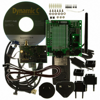
KIT DEV RCM5400W US/INTERNATIONL
Manufacturer
Rabbit Semiconductor
Series
RabbitCore 5000r
Type
Wi-Fi / 802.11.br
Datasheet
1.20-101-1246.pdf
(120 pages)
Specifications of 101-1262
Frequency
2.4GHz
Wireless Frequency
73.73 MHz
For Use With/related Products
RCM5400W
Lead Free Status / RoHS Status
Request inventory verification / Request inventory verification
Other names
101-1263
316-1138
316-1138


B.4 Using the Prototyping Board
The Prototyping Board is actually both a demonstration board and a prototyping board. As
a demonstration board, it can be used to demonstrate the functionality of the RCM5400W
right out of the box without any modifications to either board.
The Prototyping Board comes with the basic components necessary to demonstrate the
operation of the RCM5400W. Two LEDs (DS2 and DS3) are connected to PB2 and PB3,
and two switches (S2 and S3) are connected to PB4 and PB5 to demonstrate the interface
to the Rabbit 5000 microprocessor. Reset switch S1 is the hardware reset for the
RCM5400W.
The Prototyping Board provides the user with RCM5400W connection points brought out
conveniently to labeled points at header J2 on the Prototyping Board. Although header J2
is unstuffed, a 2 × 25 header is included in the bag of parts. RS-232 signals (Serial Ports C
and D) are available on header J4. A header strip at J4 allows you to connect a ribbon cable,
and a ribbon cable to DB9 connector is included with the Development Kit. The pinouts for
these locations are shown in Figure B-4.
Figure B-4. Prototyping Board Pinout
The analog signals are brought out to labeled points at header location J3 on the Prototyping
Board. Although header J3 is unstuffed, a 2 × 7 header can be added. Note that analog
signals are not available when the RCM5400W included in the Development Kit installed.
OEM User’s Manual
97
Related parts for 101-1262
Image
Part Number
Description
Manufacturer
Datasheet
Request
R

Part Number:
Description:
COMPUTER SNGLBD BL2120 FRCTNLOCK
Manufacturer:
Rabbit Semiconductor
Datasheet:

Part Number:
Description:
KIT APPLCTN RABBITCORE RCM4010
Manufacturer:
Rabbit Semiconductor
Datasheet:

Part Number:
Description:
KIT MESH NETWORK ADD-ON RCM4510W
Manufacturer:
Rabbit Semiconductor
Datasheet:

Part Number:
Description:
KIT DEV FOR BL2500 COYOTE
Manufacturer:
Rabbit Semiconductor
Datasheet:

Part Number:
Description:
KIT APPLICATION SIMPLE SENSOR
Manufacturer:
Rabbit Semiconductor
Datasheet:

Part Number:
Description:
DEV KIT DELUXE MINICORE RCM5600W
Manufacturer:
Rabbit Semiconductor
Datasheet:


Part Number:
Description:
KIT FOR BL4S100 STARTER PACKAGE
Manufacturer:
Rabbit Semiconductor
Datasheet:

Part Number:
Description:
DEV KIT STANDARD MINI RCM5600W
Manufacturer:
Rabbit Semiconductor
Datasheet:

Part Number:
Description:
MODULE RABBITCORE RCM3720
Manufacturer:
Rabbit Semiconductor
Datasheet:
Part Number:
Description:
MODULE RABBITCORE RCM3220
Manufacturer:
Rabbit Semiconductor
Datasheet:
Part Number:
Description:
MODULE RABBITCORE RCM3210
Manufacturer:
Rabbit Semiconductor
Datasheet:
Part Number:
Description:
COMPUTER SGL-BOARD OP6600 W/SRAM
Manufacturer:
Rabbit Semiconductor
Datasheet:
Part Number:
Description:
COMPUTER SGL-BD BL2000 SRAM/FLSH
Manufacturer:
Rabbit Semiconductor