AA003257-G Navman Wireless, AA003257-G Datasheet - Page 11
AA003257-G
Manufacturer Part Number
AA003257-G
Description
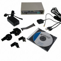
DEV KIT FOR JUPITER 32XLP
Manufacturer
Navman Wireless
Type
Receiver, GPSr
Specifications of AA003257-G
Frequency
1575.42MHz
For Use With/related Products
Jupiter 32 XLP
Lead Free Status / RoHS Status
Lead free / RoHS Compliant
Other names
943-1001
Available stocks
Company
Part Number
Manufacturer
Quantity
Price
Company:

Part Number:
AA003257-G
Manufacturer:
Navman Wireless
Quantity:
135


5.2 Data input output specifications
All communications between the Jupiter 32 xLP receiver and external devices are through the
I/O surface mount pads. These provide the contacts for power, ground, serial I/O and control.
Power requirements are discussed in Section 5.1.
LA000267D © 2008 Navman Wireless OEM. All rights reserved. Proprietary information and specifications subject to change without notice.
5.1.6 Antenna gain
The receiver will operate with a passive antenna with unity gain. However, GPS performance
will be optimum when an active antenna is used. The gain of this antenna at the input of the
module should ideally be 16 dB.
Recommendations for antenna use and testing are available in the Jupiter 32 Integrator’s
manual (LA000605).
5.1.7 Burnout protection
The receiver accepts without risk of damage a signal of +10 dBm from 0 to 2 GHz carrier
frequency, except in band 1560 to 1590 MHz where the maximum level is –10 dBm.
5.1.8 Jamming performance
The typical jamming performance of the receiver based upon a 3 dB degradation in C/N
performance is shown in Table 5-2. This is with reference to the external antenna.
5.1.9 Flash upgradability
The firmware programmed in the Flash memory may be upgraded via the serial port RXA
pad D5. The user can control this by driving the Serial BOOT SELECT pad C4 high at
startup, then downloading the code from a PC with suitable software (e.g. SiRFFlash). In
normal operation this pad should be left floating for minimal current drain. It is recommended
that in the user’s application, the BOOT SELECT pad is connected to a test pad for use in
future software upgrades.
5.1.10 Reset input
This active low input to N_RESET (pad E5) allows the user to restart the software from an
external signal. In normal operation this pad should be left floating or activated by an open
drain driver. Active pull-up is not recommended.
Table 5-2: Typical jamming performance
Frequency MHz
1425.42
1575.42
1625.42
1725.42
1400
1530
1555
200
400
800
Jamming signal power
dBm
–44
–97
–11
–9
–2
–2
–4
–2
3
4
0
11
Related parts for AA003257-G
Image
Part Number
Description
Manufacturer
Datasheet
Request
R

Part Number:
Description:
ANTENNA GPS ACTIVE 5M CABLE
Manufacturer:
Navman Wireless
Datasheet:

Part Number:
Description:
DEV KIT FOR JUPITER 30XLP
Manufacturer:
Navman Wireless
Datasheet:

Part Number:
Description:
DEV KIT FOR JUPITER 3 AND J3-30
Manufacturer:
Navman Wireless
Datasheet:

Part Number:
Description:
TERMINAL MDT-860 MOBILE DATA
Manufacturer:
Navman Wireless
Datasheet:


Part Number:
Description:
MODULE GPS RECEIVER JUPITER 3
Manufacturer:
Navman Wireless
Datasheet:

Part Number:
Description:
MODULE GPS JUPITER 30XLP 20CH
Manufacturer:
Navman Wireless
Datasheet:

Part Number:
Description:
MODULE GPS JUPITER 32XLP 20CH
Manufacturer:
Navman Wireless
Datasheet:

Part Number:
Description:
MODULE GPS RECEIVER JUPITER 3-30
Manufacturer:
Navman Wireless
Datasheet:

Part Number:
Description:
MODULE JUPITER 31 GPS W/R/A OSX
Manufacturer:
Navman Wireless
Datasheet:

Part Number:
Description:
MODULE GPS RECEIVER JUPITER 2
Manufacturer:
Navman Wireless
Datasheet:

Part Number:
Description:
DEV KIT FOR MDT860
Manufacturer:
Navman Wireless
Datasheet:

Part Number:
Description:
EVAL KIT GPS JUPITER 2
Manufacturer:
Navman Wireless
Datasheet: