MDEV-GPS-SR Linx Technologies Inc, MDEV-GPS-SR Datasheet - Page 2
MDEV-GPS-SR
Manufacturer Part Number
MDEV-GPS-SR
Description
KIT MASTER DEV GPS SR SERIES
Manufacturer
Linx Technologies Inc
Type
GPSr
Specifications of MDEV-GPS-SR
Frequency
1575.42GHz
Operating Voltage
3 V to 4.3 V
Operating Current
31 mA
Frequency Range
1575.42 MHz
Interface Type
USB
Operating Temperature Range
- 30 C to + 85 C
For Use With/related Products
SR Series
Lead Free Status / RoHS Status
Lead free / RoHS Compliant
Lead Free Status / RoHS Status
Lead free / RoHS Compliant, Lead free / RoHS Compliant


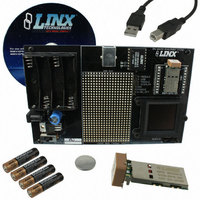
SR SERIES RECEIVER DEVELOPMENT BOARD
1.
2.
3.
4.
5.
6.
7.
8.
9.
10.
11.
TROUBLESHOOTING
Page 2
Figure 1: SR Series Receiver Development Board
• Check the batteries to make sure they are not dead.
• Check to make sure that the power switch is in the correct position.
• Make sure that the jumper is set correctly.
2
If the board fails to work out of the box, then try the following:
If all of these appear to be in order, please call 800-736-6677 or e-mail
techsupport@linxtechnologies.com for technical support.
3
Four AAA Batteries
DC Power Jack
Power Switch
Voltage Regulator
USB Interface Module
Prototype Area
Break-Out Header
SR Series Receiver Daughter Board
CR2032 Backup Battery (on the back)
OLED Display
OLED Display Power Switch
4
1
6
7
5
10
8
9
11
INITIAL SETUP
THE PROTOTYPING AREA
Figure 2: The Development Board Prototyping Area
Unpack the development system and install the AAA and coin-cell batteries. The
power switch can select between the battery pack / DC power jack or USB if the
board is plugged into a USB bus. To use the display, turn the OLED display
power switch on. The development board is now ready for use. After turning on
the power, the module will determine its current position. Please note, the time
required for an initial fix or after long periods of storage will be considerably
greater than in subsequent operation. Please refer to the module’s data guide for
complete information regarding time-to-first-fix (TTFF). To protect the display
and extend its life, turn the display off before turning the board off.
In addition to its evaluation functions, the board may also be used for actual
product development. It features a prototyping area to facilitate the addition of
application-specific circuitry. The prototyping area contains a large area of plated
through-holes so that external circuitry can be placed on the board. The holes
are set at 0.100” on center with a 0.040” diameter, making it easy to add most
industry-standard SIP and DIP packages to the board.
External circuitry can be easily interfaced with the SR receiver through the
breakout header (J7) to the right of the prototyping area. A jumper shunt has
been provided to control the routing of data into the GPS module. By default the
jumper is set for operation with the on-board USB module. When communicating
with the GPS module using your own components this jumper shunt should be
removed. At the bottom of the prototyping area is a row connected to the 3V
power supply and at the top is a row connected to ground.
NOTE: The on-board 3-volt regulator has approximately 300mA of headroom available for
additional circuitry. If added circuitry requires a higher current, the user must add an
additional regulator to the prototype area or power the board from an external supply.
Ground Bus
+3 Volt Bus
Page 3
Related parts for MDEV-GPS-SR
Image
Part Number
Description
Manufacturer
Datasheet
Request
R

Part Number:
Description:
KIT MASTER 900MHZ HP-3 SIP RS232
Manufacturer:
Linx Technologies Inc
Datasheet:

Part Number:
Description:
DEV SYSTEM MS SERIES 418MHZ
Manufacturer:
Linx Technologies Inc
Datasheet:

Part Number:
Description:
DEV SYSTEM HS SERIES 418MHZ
Manufacturer:
Linx Technologies Inc
Datasheet:

Part Number:
Description:
KIT MASTER DEV 916MHZ ES RS232
Manufacturer:
Linx Technologies Inc
Datasheet:

Part Number:
Description:
KIT DEV MASTER USB QS SERIES
Manufacturer:
Linx Technologies Inc
Datasheet:

Part Number:
Description:
KIT MASTER DEV MS KEYFOB 418MHZ
Manufacturer:
Linx Technologies Inc
Datasheet:

Part Number:
Description:
KIT DEV MS HANDHELD TX 418MHZ
Manufacturer:
Linx Technologies Inc
Datasheet:
Part Number:
Description:
KIT MASTER DEV MS KEYFOB 433MHZ
Manufacturer:
Linx Technologies Inc
Datasheet:

Part Number:
Description:
KIT DEV TX 433MHZ HS COMPACT
Manufacturer:
Linx Technologies Inc
Datasheet:

Part Number:
Description:
KIT DEV TX 418MHZ HS COMPACT
Manufacturer:
Linx Technologies Inc
Datasheet:

Part Number:
Description:
MODULE USB LOW SPEED
Manufacturer:
Linx Technologies Inc
Datasheet:

Part Number:
Description:
IC TRANSCODER MT BI-DIR 20-SSOP
Manufacturer:
Linx Technologies Inc
Datasheet:

Part Number:
Description:
IC ENCODER LOW SECURITY 8DIP
Manufacturer:
Linx Technologies Inc
Datasheet:

Part Number:
Description:
IC DECODER MS SERIES 20-SSOP
Manufacturer:
Linx Technologies Inc
Datasheet:
Part Number:
Description:
IC ENCODER MS SERIES 20-SSOP
Manufacturer:
Linx Technologies Inc
Datasheet: