MDEV-GPS-SR Linx Technologies Inc, MDEV-GPS-SR Datasheet - Page 3
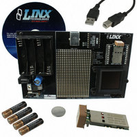
MDEV-GPS-SR
Manufacturer Part Number
MDEV-GPS-SR
Description
KIT MASTER DEV GPS SR SERIES
Manufacturer
Linx Technologies Inc
Type
GPSr
Specifications of MDEV-GPS-SR
Frequency
1575.42GHz
Operating Voltage
3 V to 4.3 V
Operating Current
31 mA
Frequency Range
1575.42 MHz
Interface Type
USB
Operating Temperature Range
- 30 C to + 85 C
For Use With/related Products
SR Series
Lead Free Status / RoHS Status
Lead free / RoHS Compliant
Lead Free Status / RoHS Status
Lead free / RoHS Compliant, Lead free / RoHS Compliant


THE GPS RECEIVER SECTION
THE USB SECTION
Page 4
Figure 3: The Development Board GPS Receiver Section
The receiver module is mounted on a daughter board which plugs into headers
on the main development board.
On the bottom of the main board is a CR2032 coin cell battery that provides
power to the RTC and SRAM when the receiver is powered down. This allows
the receiver to start up and obtain a position fix faster. This cell will provide about
two years of operation.
The development board features a Linx QS Series USB module for interface to
a PC. This allows the board to be used with the supplied development software
or with custom software developed by the user.
Drivers for the USB module are included on the
software CD in the kit or may be downloaded
from
information on using the QS Series USB module
can also be found on the website.
The USB connection also allows the board to be
powered by the USB bus instead of batteries.
This can be convenient during development to
eliminate
replacement.
Output data from the GPS module is connected
directly to the USB module, but data into the GPS
module is split. This is to prevent data collisions
between the USB module and any circuitry added
to the prototyping area. To route serial data from
the USB module to the serial data receive line on
the GPS module, use the supplied jumper to
connect the TX USB and RX MODULE lines on
the breakout header as shown in the adjoining
diagram. Remove this jumper for use with
external circuitry. The pin marked TX DISPLAY is
for Linx use and should be left unconnected.
www.linxtechnologies.com.
the
need
for
frequent
Additional
battery
Figure 5: Jumper Configuration
Figure 4: The USB Section
TX MODULE
TX USB
RX MODULE
TX DISPLAY
1PPS
RFPWRUP
EN/ON_OFF
THE DISPLAY SECTION
MASTER DEVELOPMENT SOFTWARE
Figure 6: The Development Board Display Section
The SR Series Master Development System features an OLED screen that
displays the navigation information from the GPS module. This allows the
development board to act as a stand-alone evaluation system without the need
for any additional software.
The display is driven by an on-board microcontroller located under the display.
Data from the GPS module is connected directly to this microcontroller. The
microcontroller receives data at the receiver’s default 9,600bps. If the receiver’s
baud rate is changed, it will not be able to communicate with the
microcontroller.
The display and microcontroller pull about 100mA when fully powered, so a
power switch is supplied to deactivate the display area when not in use, saving
battery life. To protect the display and extend its life, be sure to turn the display
section off before turning off the main power to the board.
The development system is supplied with Windows-based software that
communicates with the development board through the USB module. This
software displays the information from the GPS module in the different NMEA
formats and the satellite information, signal strength, and positions are displayed
graphically. If the PC is connected to the internet, the software plots the current
location on Google Maps. Full details are in the software’s User’s Guide.
Figure 7: Master Development Software
Page 5
Related parts for MDEV-GPS-SR
Image
Part Number
Description
Manufacturer
Datasheet
Request
R

Part Number:
Description:
KIT MASTER 900MHZ HP-3 SIP RS232
Manufacturer:
Linx Technologies Inc
Datasheet:

Part Number:
Description:
DEV SYSTEM MS SERIES 418MHZ
Manufacturer:
Linx Technologies Inc
Datasheet:

Part Number:
Description:
DEV SYSTEM HS SERIES 418MHZ
Manufacturer:
Linx Technologies Inc
Datasheet:

Part Number:
Description:
KIT MASTER DEV 916MHZ ES RS232
Manufacturer:
Linx Technologies Inc
Datasheet:

Part Number:
Description:
KIT DEV MASTER USB QS SERIES
Manufacturer:
Linx Technologies Inc
Datasheet:

Part Number:
Description:
KIT MASTER DEV MS KEYFOB 418MHZ
Manufacturer:
Linx Technologies Inc
Datasheet:

Part Number:
Description:
KIT DEV MS HANDHELD TX 418MHZ
Manufacturer:
Linx Technologies Inc
Datasheet:
Part Number:
Description:
KIT MASTER DEV MS KEYFOB 433MHZ
Manufacturer:
Linx Technologies Inc
Datasheet:

Part Number:
Description:
KIT DEV TX 433MHZ HS COMPACT
Manufacturer:
Linx Technologies Inc
Datasheet:

Part Number:
Description:
KIT DEV TX 418MHZ HS COMPACT
Manufacturer:
Linx Technologies Inc
Datasheet:

Part Number:
Description:
MODULE USB LOW SPEED
Manufacturer:
Linx Technologies Inc
Datasheet:

Part Number:
Description:
IC TRANSCODER MT BI-DIR 20-SSOP
Manufacturer:
Linx Technologies Inc
Datasheet:

Part Number:
Description:
IC ENCODER LOW SECURITY 8DIP
Manufacturer:
Linx Technologies Inc
Datasheet:

Part Number:
Description:
IC DECODER MS SERIES 20-SSOP
Manufacturer:
Linx Technologies Inc
Datasheet:
Part Number:
Description:
IC ENCODER MS SERIES 20-SSOP
Manufacturer:
Linx Technologies Inc
Datasheet: