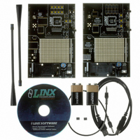
MDEV-LICAL-HS Linx Technologies Inc, MDEV-LICAL-HS Datasheet - Page 5

MDEV-LICAL-HS
Manufacturer Part Number
MDEV-LICAL-HS
Description
DEV SYSTEM HS SERIES 418MHZ
Manufacturer
Linx Technologies Inc
Type
Encoder, Decoderr
Datasheet
1.MDEV-LICAL-HS.pdf
(9 pages)
Specifications of MDEV-LICAL-HS
Supply Voltage (min)
7 V
Product
RF Development Tools
Supply Voltage (max)
16 V
Lead Free Status / RoHS Status
Contains lead / RoHS non-compliant
For Use With/related Products
HS Series Encoder and Decoder
Lead Free Status / Rohs Status
Lead free / RoHS Compliant
Other names
MDEV-LIC-HS
MDEV-LIC-HS
MDEV-LIC-HS
THE ENCODER BOARD (CONT.)
Page 8
GND
Figure 7: The Infrared Receiver Circuit
The left side of the circuit consists of an op-amp that is set up as a timer to feed
current into the phototransistor for a specific amount of time after the button is
pressed. Since the phototransistor can pick up infrared radiation from many
sources, including lights, this keeps the output from randomly switching and
keeping the encoder awake. This circuit will keep the phototransistor from
constantly pulling current and will allow the encoder to enter sleep mode,
preventing it from also constantly pulling full current.
The circuit works in the following way: when SW8 is pressed, capacitor C4 will
discharge and pull the negative input of the op amp low. This will make the
output of the op amp go high and supply current to the phototransistor (IR1). C4
will begin to recharge through R14 as soon as SW8 is released. At 5.1MΩ, it will
take approximately 20 seconds for the voltage to get high enough to make the
output of the op amp go low and deactivate IR1.
The right half of the circuit uses a comparator as a data slicer to make the output
of the phototransistor into a square wave that is easier for the encoder to read.
The output of the comparator is then connected to the KEY_IN line on the
encoder. The Master Development board has a 10kΩ resistor in series to
prevent the jack from shorting the comparator out, but it may not be necessary
in a custom design.
SW8
VCC
GND
R14
5.1M
C4
4.7uF
GND
VCC
R15
9.1M
R16
9.1M
R17
9.1M
U6
-
+
VCC
GND
GND
R19
10k
IR1
GND
R20
51k
C5
0.01uF
U6
-
+
VCC
GND
R21
100k
R18
9.1M
To KEY_IN
THE DECODER BOARD
Figure 8: The Decoder Area
The Decoder Area
The decoder board has four main sections of interest: the decoder area, the
receiver area, the USB area, and the key exchange area.
The figure below shows the decoder area of the development board.
The decoder is located in the center beneath the Linx logo. To the left are LEDs
that are connected to the decoder data lines. These will light up when the
decoder receives a signal from the encoder to take the data line high. LED D0
corresponds to data line D0, and so forth.
Beneath the decoder is an LED that is connected to the MODE_IND line. This
will light up as described in the HS Series Decoder Data Guide.
Beneath the LED are three buttons. The one on the left labeled HS_SEND_KEY
is connected to the SEND_COPY line on the decoder. The one in the middle is
connected to the LEARN line, and the one on the right is connected to the
CREATE_KEY line. The HS_SEND_KEY button will cause the decoder to begin
sending a copy of its User Data when pressed at the same time as the LEARN
button. The LEARN button is used to learn the Code Word from the encoder and,
with the other two buttons, to make the decoder enter special modes. The
CREATE_KEY button will cause the decoder to create a new key when pressed
at the same time as the LEARN button. All of these functions are described in
detail in the HS Series Decoder Data Guide.
There is one function switch to the left of the CREATE button. BSEL0 is used to
set the baud rate of the decoder as described in Table 1. *Important* The
encoder board must be set to the same baud rate in order for the signal to be
received correctly. The maximum baud rate for the LR Series is 10,000bps, so
only 4,800bps can be used on boards populated with these modules. The ES
Series receiver can use both baud rates. If the switch is up, then the line is high;
if it is down, then the line is low.
Page 9


