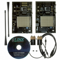
MDEV-LICAL-HS Linx Technologies Inc, MDEV-LICAL-HS Datasheet - Page 6

MDEV-LICAL-HS
Manufacturer Part Number
MDEV-LICAL-HS
Description
DEV SYSTEM HS SERIES 418MHZ
Manufacturer
Linx Technologies Inc
Type
Encoder, Decoderr
Datasheet
1.MDEV-LICAL-HS.pdf
(9 pages)
Specifications of MDEV-LICAL-HS
Supply Voltage (min)
7 V
Product
RF Development Tools
Supply Voltage (max)
16 V
Lead Free Status / RoHS Status
Contains lead / RoHS non-compliant
For Use With/related Products
HS Series Encoder and Decoder
Lead Free Status / Rohs Status
Lead free / RoHS Compliant
Other names
MDEV-LIC-HS
MDEV-LIC-HS
MDEV-LIC-HS
THE DECODER BOARD (CONT.)
Page 10
Figure 9: The Decoder Board RF Area
Figure 10: The Decoder Board USB Area
The Decoder Board RF Area
The Decoder Board USB Area
The figure below shows the RF area of the development board.
This board can be populated with either the LR Series receiver (as shown) or the
ES Series receiver. Both modules can be placed on the same pads in the center
of the section, but the ANT1 connector will be populated for the LR receiver and
the ANT2 connector will be populated for the ES receiver.
The decoder development board has a Linx SDM-USB-QS-S module for use
with the included development software. This module is powered by the USB
bus, so it will not pull any current from the battery. The figure below shows the
USB area on the decoder board.
The microcontroller on the right monitors the decoder data lines and generates
commands that are sent to the development software on the PC via the QS
Series USB module. The RX_IND LED to the left of the module will flash to
indicate that data is being received from the microcontroller.
THE DECODER BOARD (CONT.)
HS SERIES MASTER DEVELOPMENT SYSTEM SOFTWARE
Figure 11: The Decoder Board Key Exchange Area
Figure 12: The HS Series Master Development Software
The Decoder Board Key Exchange Area
The figure below shows the key exchange area of the development board.
The KEY_IN jack and the IR receiver circuit are identical to the encoder board.
Since the decoder must also send a key to an encoder and / or another decoder,
the KEY_OUT jack is populated. The infrared portion consists of an infrared
diode (IR2) that is modulated by the KEY_OUT line of the decoder. When the
SEND_KEY and LEARN buttons are pressed and released, the decoder will
begin sending the key to the jack and diode. Simply plug a wire into the
KEY_OUT jack on the decoder board and the KEY_IN jack on the encoder board
or activate the infrared receiver on the encoder board to send the key across.
The HS Series Master Development System software can be used in one of two
modes. The default mode is as a simulation of the system. This is a good way to
show how the HS Series can work in a system for activating lights and doors.
The second mode is for use with the development system. When the decoder
board is plugged into the USB port, the kit can be used to activate the features
in the software. When a data line goes high on the decoder, the microcontroller
will send a command to the computer to control the functions in the software.
Please see the documentation included with the software for details.
Page 11


