AD6655-125EBZ Analog Devices Inc, AD6655-125EBZ Datasheet - Page 60
AD6655-125EBZ
Manufacturer Part Number
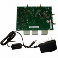
AD6655-125EBZ
Description
BOARD EVAL W/AD6655 & SOFTWARE
Manufacturer
Analog Devices Inc
Type
Receiver, CDMAr
Specifications of AD6655-125EBZ
Frequency
450MHz
Silicon Manufacturer
Analog Devices
Application Sub Type
IF Diversity Receiver
Kit Application Type
Communication & Networking
Silicon Core Number
AD6655
Kit Contents
Evaluation Board With AD6655 And Software
Lead Free Status / RoHS Status
Lead free / RoHS Compliant
For Use With/related Products
AD6655
Lead Free Status / Rohs Status
Compliant


AD6655
To avoid this additional DRVDD current, the AD6655 outputs
can be disabled at power-up by taking the OEB pin high. After
the part is placed into LVDS mode via the SPI port, the OEB
pin can be taken low to enable the outputs.
Exposed Paddle Thermal Heat Slug Recommendations
It is mandatory that the exposed paddle on the underside of the
ADC be connected to analog ground (AGND) to achieve the
best electrical and thermal performance. A continuous, exposed
(no solder mask) copper plane on the PCB should mate to the
AD6655 exposed paddle, Pin 0.
The copper plane should have several vias to achieve the lowest
possible resistive thermal path for heat dissipation to flow through
the bottom of the PCB. These vias should be filled or plugged with
nonconductive epoxy.
To maximize the coverage and adhesion between the ADC
and the PCB, a silkscreen should be overlaid to partition the
continuous plane on the PCB into several uniform sections.
This provides several tie points between the ADC and the PCB
during the reflow process. Using one continuous plane with no
partitions guarantees only one tie point between the ADC and
the PCB. See the evaluation board for a PCB layout example.
For detailed information about packaging and PCB layout of
chip scale packages, refer to Application Note AN-772, A Design
and Manufacturing Guide for the Lead Frame Chip Scale Package
(LFCSP) (see www.analog.com).
Rev. A | Page 60 of 88
CML
The CML pin should be decoupled to ground with a 0.1 μF
capacitor, as shown in Figure 48.
RBIAS
The AD6655 requires that a 10 kΩ resistor be placed between
the RBIAS pin and ground. This resistor sets the master current
reference of the ADC core and should have at least a 1% tolerance.
Reference Decoupling
The VREF pin should be externally decoupled to ground with
a low ESR, 1.0 μF capacitor in parallel with a low ESR, 0.1 μF
ceramic capacitor.
SPI Port
The SPI port should not be active during periods when the full
dynamic performance of the converter is required. Because the
SCLK, CSB, and SDIO signals are typically asynchronous to the
ADC clock, noise from these signals can degrade converter
performance. If the on-board SPI bus is used for other devices,
it may be necessary to provide buffers between this bus and the
AD6655 to keep these signals from transitioning at the converter
inputs during critical sampling periods.
Related parts for AD6655-125EBZ
Image
Part Number
Description
Manufacturer
Datasheet
Request
R

Part Number:
Description:
BOARD EVAL FOR 150MSPS AD6655
Manufacturer:
Analog Devices Inc
Datasheet:

Part Number:
Description:
±1.7g Dual-Axis IMEMS Accelerometer Evaluation Board
Manufacturer:
Analog Devices Inc
Datasheet:

Part Number:
Description:
Inertial Sensor Evaluation System
Manufacturer:
Analog Devices Inc
Datasheet:
Part Number:
Description:
Manufacturer:
Analog Devices Inc
Datasheet:
Part Number:
Description:
Manufacturer:
Analog Devices Inc
Datasheet:
Part Number:
Description:
Manufacturer:
Analog Devices Inc
Datasheet:
Part Number:
Description:
Manufacturer:
Analog Devices Inc
Datasheet:
Part Number:
Description:
Manufacturer:
Analog Devices Inc
Datasheet:
Part Number:
Description:
Manufacturer:
Analog Devices Inc
Datasheet:
Part Number:
Description:
Manufacturer:
Analog Devices Inc
Datasheet:
Part Number:
Description:
Manufacturer:
Analog Devices Inc
Datasheet:
Part Number:
Description:
Manufacturer:
Analog Devices Inc
Datasheet:
Part Number:
Description:
Manufacturer:
Analog Devices Inc
Datasheet: