STEVAL-TDR003V1 STMicroelectronics, STEVAL-TDR003V1 Datasheet
STEVAL-TDR003V1
Specifications of STEVAL-TDR003V1
Available stocks


Related parts for STEVAL-TDR003V1


STEVAL-TDR003V1 Summary of contents
Page 1
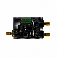
... max APC ■ BeO free amplifier ■ RoHS compliant Description The STEVAL-TDR003V1 is a 2-stage RF power amplifier including output low-pass filter (LPF) for harmonics rejection, specifically designed for portable two-way VHF radio communication. March 2009 STEVAL-TDR003V1 Mechanical specification mm Table 1. Device summary ...
Page 2
... Maximum ratings . . . . . . . . . . . . . . . . . . . . . . . . . . . . . . . . . . . . . . . . . . . . 3 2 Electrical characteristics . . . . . . . . . . . . . . . . . . . . . . . . . . . . . . . . . . . . . 3 3 Typical performance . . . . . . . . . . . . . . . . . . . . . . . . . . . . . . . . . . . . . . . . . 4 4 Circuit layout . . . . . . . . . . . . . . . . . . . . . . . . . . . . . . . . . . . . . . . . . . . . . . . 9 5 Circuit schematic . . . . . . . . . . . . . . . . . . . . . . . . . . . . . . . . . . . . . . . . . . 10 6 Package mechanical data . . . . . . . . . . . . . . . . . . . . . . . . . . . . . . . . . . . . 12 6.1 PowerFLAT™ mechanical data . . . . . . . . . . . . . . . . . . . . . . . . . . . . . . . . 13 6.1.1 6.2 Thermal pad and via design SOT- 6.2.1 7 Revision history . . . . . . . . . . . . . . . . . . . . . . . . . . . . . . . . . . . . . . . . . . . 19 2/20 Mounting indications . . . . . . . . . . . . . . . . . . . . . . . . . . . . . . . . . . . . . . . 15 Soldering profile . . . . . . . . . . . . . . . . . . . . . . . . . . . . . . . . . . . . . . . . . . . 17 STEVAL-TDR003V1 ...
Page 3
... STEVAL-TDR003V1 1 Electrical data 1.1 Maximum ratings Table 2. Absolute maximum ratings Symbol CASE Electrical characteristics T = +25 ° Table 3. Electrical specification Symbol Freq. Frequency range OUT TOTAL OUT PAE @ P OUT VAPC @ P OUT Harmonics @ P OUT Parameter Supply voltage Drain current Operating case temperature Max. ambient temperature = 7 ...
Page 4
... Pin = 8dBm 4/20 Figure (%) 5 dBm 54 Id (A) 8 dBm 52 50 165 170 175 135 Vdd = 7.2V Pout = 5W V adjusted APC 160 170 180 Pin = 5dBm STEVAL-TDR003V1 Efficiency vs frequency Eff (A) 5 dBm Eff (%) 8 dBm 140 145 150 155 160 165 Freq. (MHz) 170 175 ...
Page 5
... STEVAL-TDR003V1 Figure 4. Gain vs input power Input Pow er (dBm ) 135 MHz 155 MHz Figure 6. Gain vs input power Figure 7. Drain current vs output power 2 1.6 1.2 0.8 0 Output Pow er (dBm ) 135 MHz 155 MHz Figure Vdd = 7.2V 32 Idq = 100m 175 MHz Input Power (dBm) ...
Page 6
... Typical performance Figure 9. S21 response - low pass filter 0 -10 -20 -30 -40 -50 -60 -70 -80 -90 -100 0 6/20 500000000 1000000000 Frequency (Hz) STEVAL-TDR003V1 1500000000 2000000000 ...
Page 7
... STEVAL-TDR003V1 Table 4. Component list Designator Manufacturer C1, C5, C16 Murata C6 Murata C1F Murata C2, C3, C4, C7, Murata C8, C9, C10 C2F Murata C3F Murata C4F, C6F Murata C5F, C12 Murata C7F Murata C11 Murata C13 Murata C14 Murata C15 Murata DC-CON1 Phoenix contact L1 Coilcraft ...
Page 8
... TL2 TL3 TL4 TL5 TL6 TL7 TL8 TL9 8/20 Size Value Comment mil Substrate 0.9 2mm Ω 0. Ω 7 0. Ω 6.2 3mm Ω 6. 0. Ω Transmission line Ω 2 0. Ω 0. Ω 12 0. Ω STEVAL-TDR003V1 Part number SMA 142-0701-801 FR-4 ...
Page 9
... STEVAL-TDR003V1 4 Circuit layout Figure 10. Test fixture component layout Figure 11. Test circuit photomaster Circuit layout 9/20 ...
Page 10
... Circuit schematics 5 Circuit schematics Figure 12. Circuit schematic Figure 13. Bias schematic Figure 14. Filter schematic 10/20 STEVAL-TDR003V1 ...
Page 11
... STEVAL-TDR003V1 Figure 15. Input matching schematic Figure 16. Inter matching schematic Figure 17. Output matching schematic Circuit schematics 11/20 ...
Page 12
... Package mechanical data 6 Package mechanical data In order to meet environmental requirements, ST offers these devices in different grades of ® ECOPACK packages, depending on their level of environmental compliance. ECOPACK specifications, grade definitions and product status are available at: www.st.com. ECOPACK trademark. 12/20 STEVAL-TDR003V1 ® ...
Page 13
... STEVAL-TDR003V1 6.1 PowerFLAT™ mechanical data Table 5. PowerFLAT™ mechanical data Dim Figure 18. PowerFLAT™ package dimensions mm Min Typ Max 0.90 1.00 0.02 0.05 0.24 0.15 0.25 0.35 0.43 0.51 0.58 0.64 0.71 0.79 5.00 0.30 5.00 2.49 2.57 2.64 1.27 3 ...
Page 14
... Table 6. PowerFLAT™ tape and reel dimensions Dim Figure 19. PowerFLAT™ tape and reel 14/20 mm. Min Typ Max 5.15 5.25 5.35 5.15 5.25 5.35 1.0 1.1 1.2 STEVAL-TDR003V1 inch Min Typ Max 0.12 0.13 0.13 0.12 0.13 0.13 0.02 0.02 0.02 ...
Page 15
... STEVAL-TDR003V1 6.1.1 Mounting indications Figure 20. Standard SMD mounting Package mechanical data 15/20 ...
Page 16
... The via pattern is based on through-hole vias with 0.203 mm to 0.330 mm finished hole size 1.2 mm grid pattern with 0.025 plating on via walls. If micro vias are used in a design suggested that the quantity of vias be increased by a 4:1 ratio to achieve similar results. Figure 21. Pad layout details 16/20 STEVAL-TDR003V1 ...
Page 17
... STEVAL-TDR003V1 6.2.1 Soldering profiles Figure 22 shows the recommended solder profile for devices that have lead-free terminal plating and where a lead-free solder is used. Figure 22. Recommended solder profile - lead-free Figure 23 gives the recommended solder profile for devices with lead-free terminal plating used with leaded solder, or for devices with leaded terminal plating used with leaded solder. ...
Page 18
... Package mechanical data Figure 24. Reel information 18/20 STEVAL-TDR003V1 ...
Page 19
... STEVAL-TDR003V1 7 Revision history Table 7. Document revision history Date 27-Feb-2008 24-Mar-2009 Revision 1 Initial release 2 Updated coverpage Revision history Changes 19/20 ...
Page 20
... Australia - Belgium - Brazil - Canada - China - Czech Republic - Finland - France - Germany - Hong Kong - India - Israel - Italy - Japan - Malaysia - Malta - Morocco - Singapore - Spain - Sweden - Switzerland - United Kingdom - United States of America 20/20 Please Read Carefully: © 2009 STMicroelectronics - All rights reserved STMicroelectronics group of companies www.st.com STEVAL-TDR003V1 ...