DR-TRC104-2400-DK RFM, DR-TRC104-2400-DK Datasheet - Page 14
DR-TRC104-2400-DK
Manufacturer Part Number
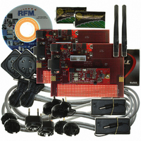
DR-TRC104-2400-DK
Description
KIT DEV FOR TRC104
Manufacturer
RFM
Type
Transceiverr
Datasheets
1.DR-TRC104-2400-DK.pdf
(33 pages)
2.DR-TRC104-2400-DK.pdf
(1 pages)
3.DR-TRC104-2400-DK.pdf
(2 pages)
Specifications of DR-TRC104-2400-DK
Frequency
2.4GHz
For Use With/related Products
TRC104
Lead Free Status / RoHS Status
Lead free / RoHS Compliant
Other names
583-1137


5 Data Transfer Modes
The TRC104 supports two data transfer modes - Continuous Data Mode and Burst Data Mode. The data transfer
mode is selected by the D_Mode bit in configuration register 0x02.
5.1 Continuous Data Mode
Continuous Data Mode is selected when the D_Mode bit of register 0x02 is set to 0. Continuous Receive Mode
routes demodulated data directly to the SDAT pin and the associated clock to the SCLK pin. In Continuous
transmit mode the data bit stream is applied directly to the SDAT pin. The internal FIFOs and the automatic
packet features are disabled in Continuous Data Mode. It is the responsibility of the TRC104 host microcontroller
to handle these functions.
5.1.1 Continuous Transmit Mode
Continuous Transmit Mode is enabled when the C_Mode bit of register 0x00 is set to 1 and the D_Mode bit of
register 0x02 is set to 0. In Continuous Transmit Mode, the transmit FIFO and all automatic packet features
including preamble generation, addressing, DC-balanced data scrambling and CRC generation are disabled. The
TRC104 host microcontroller must handle these functions for Continuous Transmit Mode. Specifically, the host
microcontroller must generate a 1-0-1-0 … preamble sequence of at least 16 bits followed immediately by the
destination address for the transmission (called the sender or local device address at the destination node).
Also for this mode, it is the responsibility of the host microcontroller to maintain correct bit timing to an accuracy of
1% as there is no bit clock output for transmit timing. The host microcontroller must be powerful enough to
accurately support the selected serial data rate (250 kb/s or 1 Mb/s) in addition to other functions required for the
end application. Figure 11and Table 10 show the timing for transmitting data on SDAT. Note that three 1 dummy
bits must be sent prior to sending the preamble and the rest of the packet.
The TRC104 should not be active for more than 4 ms at a time to allow for internal auto-calibration. Typical
calibration time is 200 µs.
5.1.2 Continuous Receive Mode
Continuous Receive Mode is enabled when the C_Mode bit of register 0x00 is set to 0 and the D_Mode bit of
register 0x02 is set to 0. In Continuous Receive Mode, the receive FIFO and automatic packet features except
www.RFM.com
©2009 by RF Monolithics, Inc.
E-mail:
info@rfm.com
Item
T1
T2
T3
Description
MODE to 1
Dummy Bits
RF Transmission Time
Technical support +1.800.704.6079
st
Bit Time
Figure 11
Table 10
Min
Typ
250
3
Max
4
Unit
ms
µs
bit
TRC104 - 08/13/09
Page 14 of 33
Related parts for DR-TRC104-2400-DK
Image
Part Number
Description
Manufacturer
Datasheet
Request
R

Part Number:
Description:
ASH RX 115.2 KBPS 433.92 MHZ
Manufacturer:
RFM
Datasheet:

Part Number:
Description:
RFIC TRANCEIVER MULTI-CHANNEL FS
Manufacturer:
RFM
Datasheet:

Part Number:
Description:
ASH TX 115.2 KBPS 433.92 MHZ
Manufacturer:
RFM
Datasheet:
Part Number:
Description:
Filters 1602MHz BW=61MHz
Manufacturer:
RFM
Datasheet:

Part Number:
Description:
RESONATOR, SM3030-6
Manufacturer:
RFM
Datasheet:

Part Number:
Description:
RESONATOR, SM3030-6
Manufacturer:
RFM
Datasheet:

Part Number:
Description:
RESONATOR, SM3030-6
Manufacturer:
RFM
Datasheet:

Part Number:
Description:
RESONATOR, SM5035-4
Manufacturer:
RFM
Datasheet:
Part Number:
Description:
RESONATOR 418MHZ SM5035-4
Manufacturer:
RFM
Datasheet:
Part Number:
Description:
RESONATOR 315 MHZ SMD
Manufacturer:
RFM
Datasheet:
Part Number:
Description:
WiFi / 802.11 Modules 2.4 and 5.8GHz + BT
Manufacturer:
RFM
Datasheet:

Part Number:
Description:
10-Terminal Ceramic Surface-Mount Case 7 x 5 mm Nominal Footprint
Manufacturer:
RFM [RF Monolithics, Inc]
Datasheet:
Part Number:
Description:
QUAD-BAND GSM850/GSM/DCS/PCS POWER AMP MODULE
Manufacturer:
RFM [RF Monolithics, Inc]
Datasheet:
Part Number:
Description:
402 to 405 MHz Medical Band Front-end Filter
Manufacturer:
RFM [RF Monolithics, Inc]
Datasheet: