DR-TRC104-2400-DK RFM, DR-TRC104-2400-DK Datasheet - Page 32
DR-TRC104-2400-DK
Manufacturer Part Number
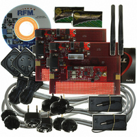
DR-TRC104-2400-DK
Description
KIT DEV FOR TRC104
Manufacturer
RFM
Type
Transceiverr
Datasheets
1.DR-TRC104-2400-DK.pdf
(33 pages)
2.DR-TRC104-2400-DK.pdf
(1 pages)
3.DR-TRC104-2400-DK.pdf
(2 pages)
Specifications of DR-TRC104-2400-DK
Frequency
2.4GHz
For Use With/related Products
TRC104
Lead Free Status / RoHS Status
Lead free / RoHS Compliant
Other names
583-1137


10 Burst Packet Mode Serial Port Message Examples
Sections 10.1 through 10.4 below provide examples of Burst Packet Mode serial port transmit and receive
messages. In each example the payload data bytes consist of the following ASCII string:
This 24 byte string in hexadecimal is:
The FIFO length is set to 24 bytes, or 0X18. The two-byte destination address used is 0XAA02, and the sender
(local device) address used is 0XAA01. Where sender address transmission is enabled, the TRC104 is also
configured to output the sender address in front of the received payload data bytes (see Section 8.6, Table 21).
10.1 Destination Address from Configuration Registers, No Sender Address
10.2 Destination Address Written by Host, No Sender Address
10.3 Destination and Sender Addresses from Configuration Registers
10.4 Destination Address Written by Host, Sender Address from Configuration Register
www.RFM.com
©2009 by RF Monolithics, Inc.
5. The host microcontroller will clock the received bits out of the FIFO.
6. Clocking bits out of the receive FIFO begins with two dummy clock cycles. The bits on these two clock
7. The first bit from the FIFO is output on the third clock. After clocking out a group of eight bits, check the
8. All bytes have now been clocked from the FIFO. In this example, the two
9. Three more clock cycles must follow the final FIFO byte in order to reset the TRC104
(stx)TRC104 Range Test Demo(etx)
02 54 52 43 31 30 34 20 52 61 6E 67 65 20 54 65 73 74 20 44 65 6D 6F 03
Transmit hex message: 02 54 52 43 31 30 34 20 52 61 6E 67 65 20 54 65 73 74 20 44 65 6D 6F 03
Receive hex message: 02 54 52 43 31 30 34 20 52 61 6E 67 65 20 54 65 73 74 20 44 65 6D 6F 03
Transmit hex message: AA 02 02 54 52 43 31 30 34 20 52 61 6E 67 65 20 54 65 73 74 20 44 65 6D 6F 03
Receive hex message: 02 54 52 43 31 30 34 20 52 61 6E 67 65 20 54 65 73 74 20 44 65 6D 6F 03
Transmit hex message: 02 54 52 43 31 30 34 20 52 61 6E 67 65 20 54 65 73 74 20 44 65 6D 6F 03
Receive hex message: AA 01 02 54 52 43 31 30 34 20 52 61 6E 67 65 20 54 65 73 74 20 44 65 6D 6F 03
Transmit hex message: AA 02 02 54 52 43 31 30 34 20 52 61 6E 67 65 20 54 65 73 74 20 44 65 6D 6F 03
Receive hex message: AA 01 02 54 52 43 31 30 34 20 52 61 6E 67 65 20 54 65 73 74 20 44 65 6D 6F 03
cycles are discarded.
INT flag line. The flag will reset after the next-to-last byte is clocked from the FIFO. At this point clock the
final eight bits from the FIFO.
Sender address bytes and the four payload data bytes will be output.
to receive the next packet. The bits on these three clock cycles are discarded.
E-mail:
info@rfm.com
Technical support +1.800.704.6079
TRC104 - 08/13/09
Page 32 of 33
Related parts for DR-TRC104-2400-DK
Image
Part Number
Description
Manufacturer
Datasheet
Request
R

Part Number:
Description:
ASH RX 115.2 KBPS 433.92 MHZ
Manufacturer:
RFM
Datasheet:

Part Number:
Description:
RFIC TRANCEIVER MULTI-CHANNEL FS
Manufacturer:
RFM
Datasheet:

Part Number:
Description:
ASH TX 115.2 KBPS 433.92 MHZ
Manufacturer:
RFM
Datasheet:
Part Number:
Description:
Filters 1602MHz BW=61MHz
Manufacturer:
RFM
Datasheet:

Part Number:
Description:
RESONATOR, SM3030-6
Manufacturer:
RFM
Datasheet:

Part Number:
Description:
RESONATOR, SM3030-6
Manufacturer:
RFM
Datasheet:

Part Number:
Description:
RESONATOR, SM3030-6
Manufacturer:
RFM
Datasheet:

Part Number:
Description:
RESONATOR, SM5035-4
Manufacturer:
RFM
Datasheet:
Part Number:
Description:
RESONATOR 418MHZ SM5035-4
Manufacturer:
RFM
Datasheet:
Part Number:
Description:
RESONATOR 315 MHZ SMD
Manufacturer:
RFM
Datasheet:
Part Number:
Description:
WiFi / 802.11 Modules 2.4 and 5.8GHz + BT
Manufacturer:
RFM
Datasheet:

Part Number:
Description:
10-Terminal Ceramic Surface-Mount Case 7 x 5 mm Nominal Footprint
Manufacturer:
RFM [RF Monolithics, Inc]
Datasheet:
Part Number:
Description:
QUAD-BAND GSM850/GSM/DCS/PCS POWER AMP MODULE
Manufacturer:
RFM [RF Monolithics, Inc]
Datasheet:
Part Number:
Description:
402 to 405 MHz Medical Band Front-end Filter
Manufacturer:
RFM [RF Monolithics, Inc]
Datasheet: