SAA6588/V2,112 NXP Semiconductors, SAA6588/V2,112 Datasheet - Page 10
SAA6588/V2,112
Manufacturer Part Number
SAA6588/V2,112
Description
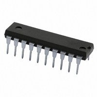
IC RDS/RBDS PRE-PROCESSOR 20DIP
Manufacturer
NXP Semiconductors
Datasheet
1.SAA6588TV2H518.pdf
(32 pages)
Specifications of SAA6588/V2,112
Function
Pre-Processor
Frequency
57kHz
Package / Case
20-DIP (0.300", 7.62mm)
Lead Free Status / RoHS Status
Lead free / RoHS Compliant
Other names
935261513112
SAA6588N
SAA6588N
SAA6588N
SAA6588N


Philips Semiconductors
The input of the pause detector (AFIN) is low-ohmic and
must be current driven (negative input of an operational
amplifier). This has the following advantages:
For combined application (RDS and AMS) variations of the
switching threshold level as well as the minimum time for
pause detection are possible via I
The level can be adjusted in four steps of 4 dB by the
control bits PL0 and PL1, see Table 8 (for 1 channel:
R = 5 k ; for 2 channels: R = 10 k
The corresponding values of FM deviation are calculated
for stereo decoders with an output voltage of 270 mV at
22.5 kHz deviation.
The minimum time for detecting a pause can be adjusted
by the control bits SOSC, PTF0 and PTF1; see Table 9.
The minimum time for detecting ‘no pause’ is fixed to 5 ms
to avoid interruptions of a pause by a short pulse.
The output signal of the pause detector is a digital
switching signal (active LOW). It is directly available via the
output pin PSWN. A detected pause may initiate an AF
search if required (FM mode).
Oscillator and clock
For good performance of the band-pass and demodulator
stages, the pre-processor requires a crystal oscillator with
a frequency of n
operated with one of four different oscillator frequencies
(n = 1 to 4). The 17.328 MHz frequency (n = 4) is also
UART interface compatible for 8051 based
microcontrollers with a 9600 baud rate (frequency
error = 4.5%), so that a radio set with microcontroller can
run in this case with one crystal only. The pre-processor
oscillator can drive the microcontroller or vice versa.
According to the used oscillator frequency, the mode
control bits PTF1, PTF0 and SOSC have to be set via the
I
The clock generator circuitry generates hereof the
internally used 4.332 MHz system clock and further
derived timing signals.
2002 Jan 14
2
C-bus after every reset, see Section “Programming”
One (MPX) as well as two (left and right) AF channel
application is possible and requires only one pin
Unwanted crosstalk is avoided if two AF channel
application is chosen
Matching the input sensitivity is possible by external
resistors.
RDS/RBDS pre-processor
4.332 MHz. The pre-processor can be
2
C-bus control.
10
Power supply and reset
The pre-processor has separate power supply inputs for
the digital and analog parts of the device. For the analog
functions an additional reference voltage (
internally generated and available via the output pin V
The I
The pre-processor generates a reset signal:
This internal reset initializes the I
as well as the I
line SDA (SDA = HIGH) for input of control mode settings
from the main controller.
If the decoder detects a reset condition, the status
information ‘reset detected’ (RSTD) is set and available via
I
decoder status register was read by the I
status information is important to signal the main controller
about a voltage drop in the pre-processor IC.
By default, the bits in the write registers (except bit SOSC)
are set to the values in Table 11. If these values are the
required values, no further initialization is necessary.
Programming
I
For communication with the external main controller
(master transceiver) the standard I
The pre-processors I
transceiver with fast mode option, that allows a transfer bit
rate up to 400 kbits/s but is also capable of operating at
lower rates ( 100 kbits/s).
The I
via the serial clock line SCL and the serial data line SDA.
The clock line is supplied by the master and is only input
for the slave transceiver. The data line is a serial 8-bit
oriented bidirectional data transfer line, and acts as input
for control mode settings from the main controller to the
pre-processor, as output for requested RDS/RBDS data
from the pre-processor to the main controller and
acknowledge between pre-processor and main controller.
2
2
C-bus request. The RSTD flag is deactivated after the
C-
After the supply voltage V
At a supply voltage drop
If the oscillator frequency is lower than 400 Hz.
BUS SLAVE TRANSCEIVER
2
2
C-bus interface is connected to the external I
C-bus interface requires a defined reset condition.
2
C-bus slave control and releases the data
2
C-bus interface acts as a slave
DDD
2
is switched on
C-bus interface registers
2
C-bus is used.
Product specification
SAA6588
2
C-bus. This
1
2
V
DDA
) is
2
C-bus
ref
.
Related parts for SAA6588/V2,112
Image
Part Number
Description
Manufacturer
Datasheet
Request
R

Part Number:
Description:
Manufacturer:
NXP Semiconductors
Datasheet:
Part Number:
Description:
NXP Semiconductors designed the LPC2420/2460 microcontroller around a 16-bit/32-bitARM7TDMI-S CPU core with real-time debug interfaces that include both JTAG andembedded trace
Manufacturer:
NXP Semiconductors
Datasheet:

Part Number:
Description:
NXP Semiconductors designed the LPC2458 microcontroller around a 16-bit/32-bitARM7TDMI-S CPU core with real-time debug interfaces that include both JTAG andembedded trace
Manufacturer:
NXP Semiconductors
Datasheet:
Part Number:
Description:
NXP Semiconductors designed the LPC2468 microcontroller around a 16-bit/32-bitARM7TDMI-S CPU core with real-time debug interfaces that include both JTAG andembedded trace
Manufacturer:
NXP Semiconductors
Datasheet:
Part Number:
Description:
NXP Semiconductors designed the LPC2470 microcontroller, powered by theARM7TDMI-S core, to be a highly integrated microcontroller for a wide range ofapplications that require advanced communications and high quality graphic displays
Manufacturer:
NXP Semiconductors
Datasheet:
Part Number:
Description:
NXP Semiconductors designed the LPC2478 microcontroller, powered by theARM7TDMI-S core, to be a highly integrated microcontroller for a wide range ofapplications that require advanced communications and high quality graphic displays
Manufacturer:
NXP Semiconductors
Datasheet:
Part Number:
Description:
The Philips Semiconductors XA (eXtended Architecture) family of 16-bit single-chip microcontrollers is powerful enough to easily handle the requirements of high performance embedded applications, yet inexpensive enough to compete in the market for hi
Manufacturer:
NXP Semiconductors
Datasheet:
Part Number:
Description:
The XA-S3 device is a member of Philips Semiconductors? XA(eXtended Architecture) family of high performance 16-bitsingle-chip microcontrollers
Manufacturer:
NXP Semiconductors
Datasheet:

Part Number:
Description:
The NXP BlueStreak LH75401/LH75411 family consists of two low-cost 16/32-bit System-on-Chip (SoC) devices
Manufacturer:
NXP Semiconductors
Datasheet:
Part Number:
Description:
The NXP LPC3130/3131 combine an 180 MHz ARM926EJ-S CPU core, high-speed USB2
Manufacturer:
NXP Semiconductors
Datasheet:
Part Number:
Description:
The NXP LPC3141 combine a 270 MHz ARM926EJ-S CPU core, High-speed USB 2
Manufacturer:
NXP Semiconductors
Part Number:
Description:
The NXP LPC3143 combine a 270 MHz ARM926EJ-S CPU core, High-speed USB 2
Manufacturer:
NXP Semiconductors

Part Number:
Description:
The NXP LPC3152 combines an 180 MHz ARM926EJ-S CPU core, High-speed USB 2
Manufacturer:
NXP Semiconductors
Part Number:
Description:
The NXP LPC3154 combines an 180 MHz ARM926EJ-S CPU core, High-speed USB 2
Manufacturer:
NXP Semiconductors