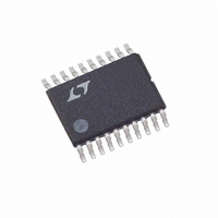
LT5503EFE#TR Linear Technology, LT5503EFE#TR Datasheet - Page 3

LT5503EFE#TR
Manufacturer Part Number
LT5503EFE#TR
Description
IC DIRECT IQ MOD/MIXER 20-TSSOP
Manufacturer
Linear Technology
Datasheet
1.LT5503EFE.pdf
(20 pages)
Specifications of LT5503EFE#TR
Function
Modulator/Mixer
Lo Frequency
1.4GHz ~ 2.4GHz
Rf Frequency
1.7GHz ~ 2.7GHz
P1db
-15dBm
Noise Floor
-152dBm/Hz
Output Power
12.7dBm
Current - Supply
38mA
Voltage - Supply
1.8 V ~ 5.25 V
Test Frequency
2.4GHz
Package / Case
20-TSSOP Exposed Pad, 20-eTSSOP, 20-HTSSOP
Pin Count
20
Screening Level
Industrial
Lead Free Status / RoHS Status
Contains lead / RoHS non-compliant
Other names
LT5503EFETR
Available stocks
Company
Part Number
Manufacturer
Quantity
Price
ELECTRICAL CHARACTERISTICS
100kHz CW signal at 1V
PARAMETER
RF Carrier Input (MODRFIN)
Frequency Range
Input VSWR
Input Power
Baseband Inputs (BI
Frequency Bandwidth (3dB)
Differential Input Voltage for 1dB Compressed Output
DC Common-Mode Voltage
Differential Input Resistance
Input Capacitance
Gain Error
Phase Error
Modulated RF Carrier Output (MODRFOUT)
Output Power, Max Gain
Output VSWR
Image Suppression
Carrier Suppression
Output 1dB Compression
Output 3rd Order Intercept
Output 2rd Order Intercept
Broadband Noise
VGA Control Logic (GC2, GC1)
Switching Time
Input Current
Input Low Voltage
Input High Voltage
Output Power Attenuation
Output Power Attenuation
Output Power Attenuation
Modulator Enable (MODEN) Low = Off, High = On
Turn ON/OFF Time
Input Current
Enable
Disable
Modulator Power Supply Requirements
Supply Voltage
Modulator Supply Current
Modulator Shutdown Current
V
CC1
= 3VDC, 2.4GHz matching, MODEN = High, GC1 = GC2 = Low, T
2
+
, BI
–
, BQ
P-P
differential, Q leads I by 90°, unless otherwise noted. (Test circuit shown in Figure 2.) (Note 3)
+
, BQ
–
)
CONDITIONS
Requires Appropriate Matching
Z
Internally Biased
Z
f
f
20MHz Offset
GC2 = Low, GC1 = High
GC2 = High, GC1 = Low
GC2 = High, GC1 = High
MODEN = High
MODEN = Low
I
I
O
O
= 100kHz, f
= 100kHz, f
(I/Q Modulator)
= 50Ω
= 50Ω
Q
Q
A
= 120kHz
= 120kHz
= 25°C, MODRFIN = 2.45GHz at –16dBm, [I – I
V
CC
MIN
– 26
– 24
1.7
1.8
– 6
– 0.4
–20 to -10
1.2 to 2.7
1.3:1
1.5:1
–142
±0.2
13.5
TYP
120
–34
–32
100
105
1.4
0.8
4.5
18
±1
–3
–3
16
29
1
2
2
9
1
B
] and [Q – Q
MAX
5.25
LT5503
0.4
0.4
38
50
dBm/Hz
UNITS
B
3
dBm
dBm
dBm
dBm
dBm
] =
MHz
V
DEG
VDC
VDC
VDC
VDC
VDC
5503f
VDC
GHz
dBc
dBc
mA
kΩ
P-P
dB
μA
dB
dB
dB
μA
μA
pF
ns
μs


