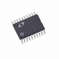
LT5503EFE#TR Linear Technology, LT5503EFE#TR Datasheet - Page 4

LT5503EFE#TR
Manufacturer Part Number
LT5503EFE#TR
Description
IC DIRECT IQ MOD/MIXER 20-TSSOP
Manufacturer
Linear Technology
Datasheet
1.LT5503EFE.pdf
(20 pages)
Specifications of LT5503EFE#TR
Function
Modulator/Mixer
Lo Frequency
1.4GHz ~ 2.4GHz
Rf Frequency
1.7GHz ~ 2.7GHz
P1db
-15dBm
Noise Floor
-152dBm/Hz
Output Power
12.7dBm
Current - Supply
38mA
Voltage - Supply
1.8 V ~ 5.25 V
Test Frequency
2.4GHz
Package / Case
20-TSSOP Exposed Pad, 20-eTSSOP, 20-HTSSOP
Pin Count
20
Screening Level
Industrial
Lead Free Status / RoHS Status
Contains lead / RoHS non-compliant
Other names
LT5503EFETR
Available stocks
Company
Part Number
Manufacturer
Quantity
Price
LT5503
ELECTRICAL CHARACTERISTICS
V
2075MHz at –12dBm. MIXRFOUT measured at 2450MHz, unless otherwise noted. (Test circuit shown in Figure 2.) (Note 3)
PARAMETER
Mixer 2nd LO Input (LO2IN)
Frequency Range
Input VSWR
Input Power
Mixer 1st LO Input (LO1IN)
Frequency Range
Input VSWR
Input 3rd Order Intercept
Mixer RF Output (MIXRFOUT)
Frequency Range
Output VSWR
Small-Signal Conversion Gain
Output Power
LO1 Suppression
Output 1dB Compression
Broadband Noise
LO2 Divider Mode Control (DMODE) Low = f
Input Current
Input Low Voltage (÷2)
Input High Voltage (÷1)
Mixer Enable (MIXEN) Low = Off, High = On
Turn ON/OFF Time
Input Current
Enable
Disable
Mixer Power Supply Requirements
Supply Voltage
Supply Current (÷2 mode)
Supply Current (÷1 mode)
Shutdown Current
Note 1: Stresses beyond those listed under Absolute Maximum Ratings
may cause permanent damage to the device. Exposure to any Absolute
Maximum Rating condition for extended periods may affect device
reliability and lifetime.
4
CC2
= 3VDC, 2.4GHz matching, MIXEN = High, DMODE = Low (LO2 ÷ 2 mode), T
2
2
LO2
÷ 2, High = f
LO2
CONDITIONS
Internally Matched
Z
Requires Appropriate Matching
Z
–30dBm/Tone, Δf = 200kHz
Requires Appropriate Matching
Z
P
20MHz Offset
DMODE = Low, MIXEN = High
DMODE = High, MIXEN = High
MIXEN = Low
÷ 1
O
O
O
LO1
(Mixer)
= 50Ω
= 50Ω
= 50Ω
= –30dBm
Note 2: External component values on the final test circuit shown in
Figure 2 are optimized for operation in the 2.4GHz to 2.5GHz band.
Note 3: Specifications over the –40°C to 85°C temperature range are
assured by design, characterization and correlation with statistical process
controls.
A
= 25°C, LO2IN = 750MHz at –18dBm, LO1IN =
V
V
CC
CC
–14.7
MIN
– 22
1.8
– 0.4
– 0.4
1400 to 2400
1700 to 2700
–20 to –12
50 to 1000
–12.7
1.4:1
1.5:1
1.5:1
–152
11.9
10.8
TYP
– 29
–15
–12
130
5
1
1
MAX
5.25
15.5
0.4
0.4
10
dBm/Hz
UNITS
dBm
dBm
dBm
dBm
MHz
MHz
MHz
VDC
VDC
VDC
VDC
VDC
5503f
dBc
mA
mA
dB
μA
μA
μA
μs


