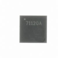
MLX71120KLQ Melexis Inc, MLX71120KLQ Datasheet - Page 13

MLX71120KLQ
Manufacturer Part Number
MLX71120KLQ
Description
RCVR FSK/FM/ASK 32-QFN
Manufacturer
Melexis Inc
Datasheet
1.MLX71120KLQ.pdf
(30 pages)
Specifications of MLX71120KLQ
Frequency
300MHz ~ 930MHz
Sensitivity
-108dBm
Data Rate - Maximum
100 kbps
Modulation Or Protocol
ASK, FM, FSK
Applications
General Remote Control, Garage Opener, RKE
Current - Receiving
8.1mA
Data Interface
PCB, Surface Mount
Antenna Connector
PCB, Surface Mount
Features
RSSI Equipped
Voltage - Supply
2.1 V ~ 5.5 V
Operating Temperature
-40°C ~ 125°C
Package / Case
32-QFN
Lead Free Status / RoHS Status
Lead free / RoHS Compliant
Memory Size
-
Other names
MLX71120A
Available stocks
Company
Part Number
Manufacturer
Quantity
Price
Company:
Part Number:
MLX71120KLQ-AAA-000-RE
Manufacturer:
MELEXIS
Quantity:
3 000
Part Number:
MLX71120KLQ-AAA-000-RE
Manufacturer:
MELEXIS/迈来芯
Quantity:
20 000
Company:
Part Number:
MLX71120KLQ-AAA-000-TU
Manufacturer:
MOT
Quantity:
314
2
Because of the double conversion architecture that employs two mixers and two IF signals, there are four
different combinations for injecting the LO1 and LO2 signals:
As a result, four different radio frequencies (RFs) could yield one and the same second IF (IF2). Fig. 9
shows this for the case of receiving at f
high) and f
bandpass shape can be achieved either with a SAW filter (featuring just a couple of MHz bandwidth), or by
the tank circuits at the LNA input and output (this typically yields 30 to 60MHz bandwidth). In any case, the
high value of the first IF (IF1) helps to suppress the image signals at f
The two remaining signals at IF1 resulting from f
mixer MIX2. This mixer features image rejection with so-called single-sideband (SSB) selection. This means
either the upper or lower sideband of IF1 can be selected. In the example of Fig. 9, LO2 high-side injection
has been chosen to select the IF2 signal resulting from f
It can be seen from the block diagram of Fig. 1 that there is a fixed relationship between the LO signal fre-
quencies (f
The IF2 frequency can be selected to 455kHz or 10.7MHz via the logic level at the IFSEL control pin. At the
same time the output impedance of the 2
description for details). Of course, also the operating frequency of the FSK demodulator (FSK DEMOD) is
set accordingly.
39010 71120
Rev. 006
Frequency Planning
LO1
RF
LO1 high side and LO2 high side: receiving at f
LO1 high side and LO2 low side:
LO1 low side and LO2 high side:
LO1 low side and LO2 low side:
(low-low) are suppressed by the bandpass characteristic provided by the RF front-end. The
Fig. 9:
, f
LO2
f
RF
) and the reference oscillator frequency f
The four receiving frequencies in a double conversion superhet receiver
f
LO1
=
f
N
RF
1
⋅
f
f
RF
LO2
LO2
nd
(high-high). In the example of Fig. 9, the image signals at f
mixer at pin MIXO is set according to the IF2 (please refer to pin
Page 13 of 30
receiving at f
receiving at f
receiving at f
RF
(high-high) and f
f
LO1
RF
(high-high).
RO
RF
RF
RF
RF
.
(high-high)
(high-low)
(low-high)
(low-low)
f
LO2
f
LO2
RF
RF
=
(low-high) and f
(high-low) are entering the second
N
f
2
FSK/FM/ASK Receiver
RF
⋅
f
RO
MLX71120
RF
300 to 930MHz
(low-low).
f
RF
Data Sheet
RF
Jun/08
(low-


