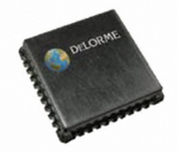
GM-205810-000 DeLorme, GM-205810-000 Datasheet - Page 7

GM-205810-000
Manufacturer Part Number
GM-205810-000
Description
MODULE GPS RCVR GPS2058
Manufacturer
DeLorme
Type
GPS Moduler
Datasheet
1.GM-205810-000.pdf
(18 pages)
Specifications of GM-205810-000
Frequency
1.575GHz
Data Rate - Maximum
57.6 kbps
Modulation Or Protocol
GPS
Applications
GPS Receiver
Current - Receiving
50mA
Data Interface
PCB, Surface Mount
Memory Size
16kB Flash
Antenna Connector
PCB, Surface Mount
Voltage - Supply
3 V ~ 3.6 V
Operating Temperature
-40°C ~ 85°C
Package / Case
40 Pin
Processor Used
STA2058
Operating Voltage
3.3 V
Operating Current
85 mA
Frequency Range
1575.42 MHz
Operating Temperature Range
- 40 C to + 85 C
Lead Free Status / RoHS Status
Lead free / RoHS Compliant
Features
-
Sensitivity
-
Lead Free Status / Rohs Status
Lead free / RoHS Compliant
For Use With/related Products
Consumer handheld, PND (portable navigation), in-vehicle navigation/telematics systems
Other names
GM-205810-000TR
Minimum Application Connectivity
The following describes the minimum GPS2058 GPS receiver module connectivity necessary to obtain a position fix with passive
antenna and host connection.
The Antenna connects to the module on the RF-input pin. It is very important that this connection maintains a 50 ohm imped-
ance with minimal discontinuities to maximize the energy transfer from the antenna to the module RF input. Both RF ground
pins (38 and 40) must be isolated from digital ground through a 100nH inductor to eliminate high frequency loop currents and
preventing self jamming from digital noise injected into the RF section or RF noise from being introduced to the digital section.
Refer to our application note titled ‘GPS Module Antenna and RF Design Guidelines’ for additional discussion and layout recom-
mendations.
Power is supplied to the module by connecting a 3.3V digital supply to pin 2. Use 0.1uF decoupling cap as close to the module
pin as possible. Pin 1 is digital ground, connect to ground plane as close to module as possible. For reducing the supply current
when an additional 1.8V supply is available, refer to the section titled “Power Supply Options” in this document.
To ensure that module powers up in the correct state, nRESET (pin 6) must be tied to 3.3V thru a 10Kohm resistor to prevent
accidental receiver reset. The WAKEUP input (pin 5) must be tied to 3.3V thru a 10Kohm resistor and the nSTDBYI input (pin 4)
must also be tied to 3.3V thru a 10K ohm resistor to hold the receiver out of standby mode. A 0.1uF cap to ground is also tied
to the nSTDBYI input to delay the ramp up to 3.3V, which brings the pin biasing up in the right sequence.
The UART0 NMEA connection is a CMOS level TTL signal level. Pin 31 is the transmit output pin for sending the NMEA data
FROM the module TO the host, and pin 30 is the receive input for sending commands FROM the host TO the Module.
The VADC input (pin 11) should also be tied to the 3.3V supply to properly bias the device. A decoupling capacitor of 0.1uF is
used as close to the pin as possible.
All other pins may remain unconnected.
Page 7


