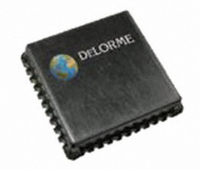
GM-205810-000 DeLorme, GM-205810-000 Datasheet - Page 9

GM-205810-000
Manufacturer Part Number
GM-205810-000
Description
MODULE GPS RCVR GPS2058
Manufacturer
DeLorme
Type
GPS Moduler
Datasheet
1.GM-205810-000.pdf
(18 pages)
Specifications of GM-205810-000
Frequency
1.575GHz
Data Rate - Maximum
57.6 kbps
Modulation Or Protocol
GPS
Applications
GPS Receiver
Current - Receiving
50mA
Data Interface
PCB, Surface Mount
Memory Size
16kB Flash
Antenna Connector
PCB, Surface Mount
Voltage - Supply
3 V ~ 3.6 V
Operating Temperature
-40°C ~ 85°C
Package / Case
40 Pin
Processor Used
STA2058
Operating Voltage
3.3 V
Operating Current
85 mA
Frequency Range
1575.42 MHz
Operating Temperature Range
- 40 C to + 85 C
Lead Free Status / RoHS Status
Lead free / RoHS Compliant
Features
-
Sensitivity
-
Lead Free Status / Rohs Status
Lead free / RoHS Compliant
For Use With/related Products
Consumer handheld, PND (portable navigation), in-vehicle navigation/telematics systems
Other names
GM-205810-000TR
In Standby mode, the CPU core is switched off to reduce power consumption. The Real Time Clock and Wake-Up logic remains
independently powered by an internal low-power voltage regulator for fast start-ups coming out of Standby mode.
The Standby mode power-down sequence may be initiated by either a software command, or by hardware control using the
nSTDBYI and WAKEUP inputs. DO NOT tie the nSTDBYI and WAKEUP pins together if you are using STANDBY mode.
Coming out of Standby mode requires the nSTDBYI and WAKEUP inputs to be in the proper state even if Standby mode was
initiated via software (see below).
The WAKEUP input must be low to initiate Standby mode. If WAKEUP is high then Standby mode cannot be initiated by any event,
software or hardware.
A Reset event (nRESET pin goes low) has priority over nSTDBYI. Therefore, reset activation will force an exit from the Standby
mode. If nRESET is activated while nSTDBYI is logic high, the device exits from Standby mode. If a Reset pulse is given while
nSTDBYI is kept at constant low level, the device will enter Standby mode again after nRESET rising edge.
The nSTDBYO output is useful as an indication of the module status – when this output is low the module is in Standby mode.
The following figure shows the sequence of events when entering Standby mode via software by sending a $PDME,13,1,#seconds
command to the GPS2058. When this command is executed the module will enter Standby mode if the WAKEUP input is low.
After the #seconds has timed out the module wakes itself up and the CPU restarts. If the #seconds is zero the module remains
in standby mode indefinitely, or until an external wake-up is initiated via the WAKEUP input or a reset event occurs.
Applying a positive pulse of 100us (minimum) on the WAKEUP pin switches the main internal voltage regulator back on and
applies power to the core. The CPU core is kept in reset mode until the internal voltage is correctly regulated, then the CPU
restarts itself.
If the nSTDBYI pin is low when the device wakes up, the module will re-enter Standby mode.
STANDBY MODE
Software STANDBY
Page 9


