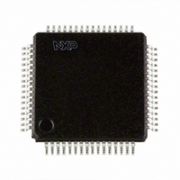
TEF6862HL/V1S,557 NXP Semiconductors, TEF6862HL/V1S,557 Datasheet - Page 8

TEF6862HL/V1S,557
Manufacturer Part Number
TEF6862HL/V1S,557
Description
IC TUNER CREST SELECTIVE 64LQFP
Manufacturer
NXP Semiconductors
Datasheet
1.TEF6862HLV1S518.pdf
(65 pages)
Specifications of TEF6862HL/V1S,557
Modulation Or Protocol
AM, FM, WB
Applications
AM/FM Radio Receiver
Current - Receiving
101.9mA
Data Interface
PCB, Surface Mount
Antenna Connector
PCB, Surface Mount
Voltage - Supply
8 V ~ 9 V
Operating Temperature
-40°C ~ 85°C
Package / Case
64-LQFP
Lead Free Status / RoHS Status
Lead free / RoHS Compliant
Features
-
Frequency
-
Sensitivity
-
Memory Size
-
Data Rate - Maximum
-
Lead Free Status / RoHS Status
Lead free / RoHS Compliant, Lead free / RoHS Compliant
Other names
935288821557
Philips Semiconductors
TEF6862_1
Product data sheet
7.10 IF filter and demodulator tuning
7.11 VCO and dividers
7.4 FM IF2 channel filter
7.5 FM limiter and level detection
7.6 FM demodulator
7.7 Audio output buffer
7.8 Tuning mute
7.9 Weather band input
The order and dynamic range of the filter is designed for operation with only one external
ceramic filter in the application. The filter characteristic is optimized to combine high
selectivity with low distortion from maximum to minimum IF bandwidth settings. The
bandwidth of the filter can be selected directly with 5 bits via the I
via the bandwidth control algorithm. When the automatic mode is selected the bandwidth
depends on the signal conditions: the amount of adjacent channel, the deviation of the
desired signal, detuning and signal strength.
The filter center frequency is I
The limiter amplifies the IF filter output signal, removes AM modulations from the IF signal
and supplies a well defined signal for the FM demodulator. From the limiter also the RSSI
is derived which is converted to a suitable level voltage with minimum temperature drift.
The fully integrated FM demodulator converts the IF signal from the limiter to the FM MPX
output signal with very low distortion. The center frequency of the filter in the demodulator
is aligned together with the IF2 filter center frequency.
The output buffer for AM and FM amplifies the demodulated signal and includes low-pass
filtering to attenuate any IF residual signals. The gain is increased in weather band
reception to compensate for the low frequency deviation.
The audio soft slope tuning mute circuit is controlled by the sequential machine for
different tuning actions to eliminate audible effects. Control signals are generated to
control the muting and the weak signal processing in the signal processor.
A separate RF input to the FM front-end mixer for weather band makes the weather band
application easier.
The center frequency as well as the bandwidth of both the IF filter and demodulator are
coupled to the stable crystal reference frequency. Fine adjustment is achieved with a 6-bit
DAA.
The varactor tuned LC oscillator together with the dividers provides the local oscillator
signal for both AM and FM front-end mixers. The VCO has an operating frequency of
approximately 160 MHz to 256 MHz. In FM mode the LO frequency is divided by 1, 2 or 3.
Rev. 01 — 14 September 2006
2
C-bus aligned with 6 bits.
Car Radio Enhanced Selectivity Tuner (CREST)
© Koninklijke Philips Electronics N.V. 2006. All rights reserved.
2
C-bus or automatically
TEF6862
8 of 65


