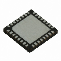
TRC105 RFM, TRC105 Datasheet - Page 34

TRC105
Manufacturer Part Number
TRC105
Description
IC TXRX 300MHZ-510MHZ 32TQFN
Manufacturer
RFM
Specifications of TRC105
Frequency
300MHz ~ 510MHz
Data Rate - Maximum
200kbps
Modulation Or Protocol
FSK, OOK
Applications
General Purpose
Power - Output
13dBm
Sensitivity
-112dBm
Voltage - Supply
2.1 V ~ 3.6 V
Current - Receiving
3mA
Current - Transmitting
30mA
Data Interface
PCB, Surface Mount
Antenna Connector
PCB, Surface Mount
Operating Temperature
-40°C ~ 85°C
Package / Case
32-TQFN
Wireless Frequency
300 MHz to 510 MHz
Output Power
13 dBm
Operating Supply Voltage
2.1 V to 3.6 V
Maximum Operating Temperature
+ 85 C
Mounting Style
SMD/SMT
Maximum Supply Current
1.7 mA
Minimum Operating Temperature
- 40 C
Modulation
FSK, OOK
Lead Free Status / RoHS Status
Lead free / RoHS Compliant
Memory Size
-
Lead Free Status / Rohs Status
Lead free / RoHS Compliant
Other names
583-1159-2
0x0E - IRQCFG0E [default 0x01]
0x0F - IRQCFG0F [default 0x00]
www.RFM.com
©2009-2010 by RF Monolithics, Inc.
Name
Start_Fill
Start_Det
TX_Stop
FIFO_OVR
RSSI_Int
SIG_DETECT
PLL_LOCK_ST
PLL_LOCK_EN
Name
RSSI_thld(7..0)
E-mail:
Bits
Bits
7..0
7
6
5
4
3
2
1
0
info@rfm.com
r/w/c
r/w/c
r/w/c
r/w/c
R/W
R/W
r/w
r/w
r/w
r/w
r
Description
FIFO fill mode selection:
0 → FIFO starts filling when start pattern is recognized
1 → FIFO fills as long as Start_Det is 1
Start of FIFO fill:
If Start_Fill = 0, goes high when start pattern recognized. Write a 1 to reset the start pattern
recognition.
If Start_Fill = 1
Transmit state:
FIFO overflow:
In Buffered data mode, writing a 1 to this bit clears the FIFO.
In Packet data mode, writing a 1 to this bit clears the FIFO and allows a new packet to be transmitted
or received immediately.
Enables SIG_DETECT when RSSI_thld is tripped:
0 → Disable interrupt
1→ Enable interrupt
Detects a signal above the RSSI_thld:
0 → Signal lower than threshold
1 → Signal equal or greater than the RSSI_thld level
This bit latches high and must be cleared by writing a 1 to its location.
Detects the PLL lock status:
0 → PLL not locked
1 → PLL locked
This bit latches high each time the PLL locks and must be cleared by writing a 1 to its location.
Enables the PLL_LOCK signal on Pin 23
0 → PLL_LOCK signal disabled, Pin 23 set high
1 → PLL_LOCK signal enabled
Description
RSSI threshold level for interrupt.
RSSI_thld default is 0x00
0 → Stop filling FIFO
1 → Start filling FIFO
0 → Transferring bits to the TX modulator
1 → Last bit transferred to the TX modulator
Technical support +1.800.704.6079
Table 29
Table 30
TRC105 - 11/01/10
Page 34 of 66


