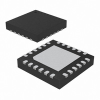
SX1231IMLTRT Semtech, SX1231IMLTRT Datasheet - Page 34

SX1231IMLTRT
Manufacturer Part Number
SX1231IMLTRT
Description
IC 433/868/915MHZ TXRX 24-QFN
Manufacturer
Semtech
Specifications of SX1231IMLTRT
Frequency
433MHz, 868MHz, 915MHz
Data Rate - Maximum
300kbps
Modulation Or Protocol
FSK, GFSK, GMSK, MSK, OOK
Applications
AMR, Home Automation, Security
Power - Output
13dBm
Sensitivity
-118dBm
Voltage - Supply
1.8 V ~ 3.6 V
Current - Receiving
16mA
Current - Transmitting
95mA
Data Interface
PCB, Surface Mount
Antenna Connector
PCB, Surface Mount
Operating Temperature
-40°C ~ 85°C
Package / Case
24-QFN
Transmitting Current
95mA
Data Rate
300Kbps
Rf Ic Case Style
QFN
No. Of Pins
24
Supply Voltage Range
1.8V To 3.6V
Operating Temperature Range
-40°C To +85°C
Receiving Current
16mA
Lead Free Status / RoHS Status
Lead free / RoHS Compliant
Memory Size
-
Lead Free Status / Rohs Status
Compliant
Other names
SX1231IMLTR
Available stocks
Company
Part Number
Manufacturer
Quantity
Price
Company:
Part Number:
SX1231IMLTRT
Manufacturer:
ATMEL
Quantity:
1 200
Part Number:
SX1231IMLTRT
Manufacturer:
SEMTECHCORPORATION
Quantity:
20 000
4.2.1. Transmitter Startup Time
The transmitter wake-up time, TS_TR, is given by the sequence controlled by the digital part. It is a pure digital delay which
depends on the bit rate and the ramp-up time. In FSK mode, this time can be derived from the following equation.
where PaRamp is the ramp-up time programmed in RegPaRamp and Tbit is the bit time.
In OOK mode, this equation can be simplified to the following:
4.2.2. Tx Start Procedure
As described in the former section, ModeReady and TxReady interrupts warn the uC that the transmitter is ready to
transmit data
4.2.3. Receiver Startup Time
It is highly recommended to use the built-in sequencer of the SX1231, to optimize the delays when setting the chip in
receive mode. It guarantees the shortest startup times, hence the lowest possible energy usage, for battery operated
systems.
The startup times of the receiver can be calculated from the following:
Rev 3 - April 2010
ADVANCED COMMUNICATIONS & SENSING
In Continuous mode, the preamble bits preceding the payload can be applied on the DIO2/DATA pin immediately after
any of these interrupts have fired. The DCLK signal, activated on pin DIO1/DCLK can also be used to start toggling the
DATA pin, as described on Figure 28.
In Packet mode, the SX1231 will automatically modulate the RF signal with preamble bytes as soon as TxReady or
ModeReady happen. The actual packet transmission (starting with the number of preambles specified in PreambleSize)
will start when the TxStartCondition is fulfilled.
ModeReady
TxReady
XO Started and PLL is locked
(sequencer or user)
Tx startup request
TS
Figure 15. Tx Startup, FSK and OOK
_
TR
group delay
Analog
5 us
=
TS
5
μ
_
s
TR
+
0.5 x Tbit
. 1
TS_TR
=
Page 34
25
5
μ
×
s
PaRamp
+
1.25 x PaRamp
1
2
(only in FSK
×
mode)
Tbit
+
1
2
×
Tbit
Transmission of Packet
,
DATASHEET
www.semtech.com
SX1231


