CYRF69103-40LFXC Cypress Semiconductor Corp, CYRF69103-40LFXC Datasheet - Page 31
CYRF69103-40LFXC
Manufacturer Part Number
CYRF69103-40LFXC
Description
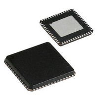
IC PROC 8K FLASH 40VQFN
Manufacturer
Cypress Semiconductor Corp
Series
CYRFr
Datasheet
1.CYRF69103-40LFXC.pdf
(68 pages)
Specifications of CYRF69103-40LFXC
Package / Case
40-VQFN Exposed Pad, 40-HVQFN, 40-SQFN, 40-DHVQFN
Frequency
2.4GHz
Data Rate - Maximum
1Mbps
Modulation Or Protocol
ISM
Applications
General Purpose
Power - Output
6dBm
Sensitivity
-87dBm
Voltage - Supply
1.8 V ~ 3.6 V
Current - Receiving
21.9mA
Current - Transmitting
39.9mA
Data Interface
PCB, Surface Mount
Memory Size
8kB Flash, 256B SRAM
Antenna Connector
PCB, Surface Mount
Operating Temperature
0°C ~ 70°C
Processor Series
CYRF691x
Core
M8C
Data Bus Width
8 bit
Data Ram Size
256 B
Interface Type
SPI
Maximum Clock Frequency
2 MHz
Number Of Programmable I/os
15
Number Of Timers
4
Operating Supply Voltage
2.5 V, 3.3 V
Maximum Operating Temperature
+ 70 C
Mounting Style
SMD/SMT
Minimum Operating Temperature
0 C
Program Memory Type
Flash
Program Memory Size
8 KB
Operating Temperature (min)
0C
Operating Temperature (max)
70C
Operating Temperature Classification
Commercial
Operating Supply Voltage (min)
1.8V
Operating Supply Voltage (typ)
2.5/3.3V
Operating Supply Voltage (max)
3.6V
Height
1 mm
Length
5.9 mm
Supply Voltage (max)
3.6 V
Supply Voltage (min)
1.8 V
Width
5.9 mm
Lead Free Status / RoHS Status
Lead free / RoHS Compliant
For Use With
770-1001 - ISP 4PORT CYPRESS ENCORE II MCU
Lead Free Status / Rohs Status
Lead free / RoHS Compliant
Other names
428-1933
Available stocks
Company
Part Number
Manufacturer
Quantity
Price

Part Number:
CYRF69103-40LFXC
Manufacturer:
CYCRESS
Quantity:
20 000


16. Reset
The microcontroller supports two types of resets: Power on Reset (POR) and Watchdog Reset (WDR). When reset is initiated, all
registers are restored to their default states and all interrupts are disabled.
The occurrence of a reset is recorded in the System Status and Control Register (CPU_SCR). Bits within this register record the
occurrence of POR and WDR Reset respectively. The firmware can interrogate these bits to determine the cause of a reset.
The microcontroller resumes execution from Flash address 0x0000 after a reset. The internal clocking mode is active after a reset,
until changed by user firmware.
Note The CPU clock defaults to 3 MHz (Internal 24 MHz Oscillator divide-by-8 mode) at POR to guarantee operation at the low V
that might be present during the supply ramp.
Table 16-1. System Status and Control Register (CPU_SCR) [0xFF] [R/W]
Document #: 001-07611 Rev *F
The bits of the CPU_SCR register are used to convey status and control of events for various functions of a CYRF69103
device.
Bit 7
Bit 6
Bit 5
Bit 4
Bit 3
Bits 2:1
Bit 0
Note
Bit #
Field
Read/Write
Default
3. C = Clear. This bit can only be cleared by the user and cannot be set by firmware.
GIES
The Global Interrupt Enable Status bit is a read-only status bit and its use is discouraged. The GIES bit is a legacy
bit, which was used to provide the ability to read the GIE bit of the CPU_F register. However, the CPU_F register
is now readable. When this bit is set, it indicates that the GIE bit in the CPU_F register is also set which, in turn,
indicates that the microprocessor services interrupts:
0 = Global interrupts disabled
1 = Global interrupt enabled
Reserved
WDRS
The WDRS bit is set by the CPU to indicate that a WDR event has occurred. The user can read this bit to
determine the type of reset that has occurred. The user can clear but not set this bit:
0 = No WDR
1 = A WDR event has occurred
PORS
The PORS bit is set by the CPU to indicate that a POR event has occurred. The user can read this bit to deter-
mine the type of reset that has occurred. The user can clear but not set this bit:
0 = No POR
1 = A POR event has occurred (Note that WDR events do not occur until this bit is cleared).
SLEEP
Set by the user to enable CPU sleep state. CPU remains in sleep mode until any interrupt is pending. The Sleep
bit is covered in more detail in the section
0 = Normal operation
1 = Sleep
Reserved
STOP
This bit is set by the user to halt the CPU. The CPU remains halted until a reset (WDR, POR, or external reset)
has taken place. If an application wants to stop code execution until a reset, the preferred method is to use the
HALT instruction rather than writing to this bit.
0 = Normal CPU operation
1 = CPU is halted (not recommended)
GIES
R
7
0
Reserved
6
–
0
WDRS
R/C
5
0
[3]
Sleep Mode
PORS
R/C
4
1
[3]
on page 32.
Sleep
R/W
3
0
Reserved
2
–
1
Reserved
1
–
0
CYRF69103
Page 31 of 68
Stop
R/W
0
0
CC
[+] Feedback
Related parts for CYRF69103-40LFXC
Image
Part Number
Description
Manufacturer
Datasheet
Request
R

Part Number:
Description:
IC PROC 8K FLASH 40-QFN
Manufacturer:
Cypress Semiconductor Corp
Part Number:
Description:
Manufacturer:
Cypress Semiconductor Corp
Datasheet:
Part Number:
Description:
Manufacturer:
Cypress Semiconductor Corp
Datasheet:
Part Number:
Description:
Manufacturer:
Cypress Semiconductor Corp
Datasheet:
Part Number:
Description:
Manufacturer:
Cypress Semiconductor Corp
Datasheet:
Part Number:
Description:
Manufacturer:
Cypress Semiconductor Corp
Datasheet: