GS-BT2416C1.AT1 STMicroelectronics, GS-BT2416C1.AT1 Datasheet - Page 11
GS-BT2416C1.AT1
Manufacturer Part Number
GS-BT2416C1.AT1
Description
BLUETOOTH CLASS 1 SPP W/SOFTWARE
Manufacturer
STMicroelectronics
Datasheet
1.GS-BT2416C1DBAT1.pdf
(38 pages)
Specifications of GS-BT2416C1.AT1
Frequency
2.4GHz
Data Rate - Maximum
721kbps
Modulation Or Protocol
Bluetooth v2.1+EDR, class 1
Applications
General Purpose
Power - Output
20dBm
Sensitivity
-84dBm
Voltage - Supply
3.3V
Current - Receiving
60mA
Current - Transmitting
180mA
Data Interface
PCB, Surface Mount
Antenna Connector
PCB, Surface Mount
Operating Temperature
-20°C ~ 70°C
Package / Case
Module
Processor Series
STLC2500
Wireless Frequency
2.4 GHz to 2.5 GHz
Interface Type
SPI, I2C, UART, PCM
Data Rate
721 Kbps
Modulation
USB, UART, PCM, SPI, IýC
Output Power
100 mW
For Use With
497-6224 - DEMO BOARD FOR GS-BT2416C2.ATI497-6223 - DEMO BOARD FOR GS-BT2416C2.H497-5792 - BOARD DEMO FOR CLASS 1 MODULES
Lead Free Status / RoHS Status
Lead free / RoHS Compliant
Memory Size
-
Lead Free Status / Rohs Status
Lead free / RoHS Compliant
Other names
497-5789


GS-BT2416C1.AT1
6.1
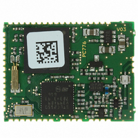
Figure 3.
Antenna on PCB
Antenna reference
RF output pin must be connected to an antenna which could be:
●
●
●
●
●
Figure 6.
Tools for calculating the characteristic impedance, based on the physical and mechanical
characteristics of the PCB, can be easily found on the web.
Trace width
PCB
thickness
Antenna directly printed on the PCB
Integrated antenna as, for example, antenova
ANCV12G44SAA127, pulse W3008, Yageo CAN4311153002451K.
External antenna connected by means a SMA connector
Despite of the type of antenna chosen, the connection between the RF out pin and the
antenna must be executed in such a way that the connection trace must be matched to
have characteristic impedance (Z0) of 50 Ω to get the maximum power transfer.
Matching for 50 Ω is depending on the various factors, elements to be taken into
consideration are:
–
–
–
–
Type of material, i.e. FR4
The electrical characteristics of the material,i.e. the εr, electric constant at
2.4 GHz
Mechanical dimensions of the PCB and traces, i.e. PCB thickness, trace/
reference ground thickness, trace width, trace thickness
Just to give an example, using a 1 mm thick FR4 board, with an εr = 4.3 at
2.4 GHz, with Cu thickness of 41 µm, the resulted width of 50 Ω strip-line is
1.9 mm (Microstrip type calculation).
Parameters for trace matching
Figure 4.
ε
r
(
Dielectric constant
Antenna examples
(Figure
3.)
)
®
30-30-A5839-01, Murata
Figure 5.
(Figure
Application information
SMA connector for
external antenna
5.)
(Figure
Reference ground
Trace thickness
4.)
11/38
Related parts for GS-BT2416C1.AT1
Image
Part Number
Description
Manufacturer
Datasheet
Request
R

Part Number:
Description:
STMicroelectronics [RIPPLE-CARRY BINARY COUNTER/DIVIDERS]
Manufacturer:
STMicroelectronics
Datasheet:
Part Number:
Description:
STMicroelectronics [LIQUID-CRYSTAL DISPLAY DRIVERS]
Manufacturer:
STMicroelectronics
Datasheet:

Part Number:
Description:
BOARD EVAL FOR MEMS SENSORS
Manufacturer:
STMicroelectronics
Datasheet:
Part Number:
Description:
NPN TRANSISTOR POWER MODULE
Manufacturer:
STMicroelectronics
Datasheet:
Part Number:
Description:
TURBOSWITCH ULTRA-FAST HIGH VOLTAGE DIODE
Manufacturer:
STMicroelectronics
Datasheet:
Part Number:
Description:
Manufacturer:
STMicroelectronics
Datasheet:
Part Number:
Description:
DIODE / SCR MODULE
Manufacturer:
STMicroelectronics
Datasheet:
Part Number:
Description:
DIODE / SCR MODULE
Manufacturer:
STMicroelectronics
Datasheet:
Part Number:
Description:
Search -----> STE16N100
Manufacturer:
STMicroelectronics
Datasheet:
Part Number:
Description:
Search ---> STE53NA50
Manufacturer:
STMicroelectronics
Datasheet:
Part Number:
Description:
NPN Transistor Power Module
Manufacturer:
STMicroelectronics
Datasheet:
Part Number:
Description:
DIODE / SCR MODULE
Manufacturer:
STMicroelectronics
Datasheet: