MC13202FC Freescale Semiconductor, MC13202FC Datasheet - Page 21
MC13202FC
Manufacturer Part Number
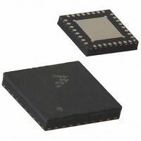
MC13202FC
Description
IC TXRX RF 2.4GHZ 32-QFN
Manufacturer
Freescale Semiconductor
Datasheet
1.MC13202FCR2.pdf
(30 pages)
Specifications of MC13202FC
Frequency
2.4GHz
Data Rate - Maximum
250kbps
Modulation Or Protocol
802.15.4
Applications
AMR, HID, HVAC, ISM
Power - Output
-27dBm ~ 3dBm
Sensitivity
-92dBm
Voltage - Supply
2 V ~ 3.4 V
Current - Receiving
37mA
Current - Transmitting
30mA
Data Interface
PCB, Surface Mount
Antenna Connector
PCB, Surface Mount
Operating Temperature
-40°C ~ 85°C
Package / Case
32-QFN
Operating Supply Voltage
2.7 V
Mounting Style
SMD/SMT
Minimum Operating Temperature
- 40 C
Operating Temperature (min)
-40C
Operating Temperature (max)
85C
Operating Temperature Classification
Industrial
Lead Free Status / RoHS Status
Lead free / RoHS Compliant
Memory Size
-
Lead Free Status / Rohs Status
Lead free / RoHS Compliant


8.3
Freescale Semiconductor
•
•
Program and use the modem IO pins properly for low power operation
— All unused modem GPIOx signals must be used one of 2 ways:
— When modem GPIO are used as outputs:
— If the modem GPIO is used as an input, the GPIO should be driven by its source during all low
— Digital outputs IRQ, MISO, and CLKO:
If the MCU is also going to be used in low power modes, be sure that all unused IO are programmed
properly for low power operation (typically best case is as outputs in the low state). The MC13202
is commonly used with the Freescale MC9S08GT/GB 8-bit devices. For these MCUs:
— Use only STOP2 and STOP3 modes (not STOP1) with these devices where the GPIO states are
— As stated above all unused GPIO should be programmed as outputs low for lowest power and
3
4
5
6
A wider frequency stability may be acceptable if application uses trimming at production final test.
A wider aging tolerance may be acceptable if application uses trimming at production final test.
Higher ESR may be acceptable with lower load capacitance.
Lower load capacitance can allow higher ESR and is better for low temperature operation in Doze mode.
Low Power Considerations
– If the Off mode is to be used as a long term low power mode, unused GPIO should be tied
– If only Hibernate and/or Doze modes are used as long term low power modes, the GPIO
– Pullup resistors should be provided (can be provided by the MCU IO pin if tied to the MCU)
– During Hibernate and/or Doze modes, the GPIO will retain its programmed output state.
power modes or a pullup resistor should be provided.
– MISO - is always an output. During Hibernate, Doze, and active modes, the default
– IRQ - is an open drain output (OD) and should always have a pullup resistor (typically
– CLKO - is always an output. During Hibernate CLKO retains its output state, but does not
retained. The MCU must retain control of the MC13202 IO during low power operation.
no floating inputs.
to ground. The default GPIO mode is an input and there will be no conflict.
should programmed as outputs in the low state.
if the modem Off condition is to be used as a long term low power mode.
condition is for the MISO output to go to tristate when CE is de-asserted, and this can cause
a problem with the MCU because one of its inputs can float. Program Control_B Register
07, Bit 11, miso_hiz_en = 0 so that MISO is driven low when CE is de-asserted. As a result,
MISO will not float when Doze or Hibernate Mode is enabled.
provided by the MCU IO). IRQ acts as the interrupt request output.
toggle. During Doze, CLKO may toggle depending on whether it is being used.
It is good practice to have the IRQ interrupt input to the MCU disabled
during the hardware reset to the modem. After releasing the modem
hardware reset, the interrupt request input to the MCU can then be enabled
to await the IRQ that signifies the modem is ready and in Idle mode; this can
prevent a possible extraneous false interrupt request.
MC13202 Technical Data, Rev. 1.5
NOTE
21
Related parts for MC13202FC
Image
Part Number
Description
Manufacturer
Datasheet
Request
R

Part Number:
Description:
Manufacturer:
Freescale Semiconductor, Inc
Datasheet:
Part Number:
Description:
Manufacturer:
Freescale Semiconductor, Inc
Datasheet:
Part Number:
Description:
Manufacturer:
Freescale Semiconductor, Inc
Datasheet:
Part Number:
Description:
Manufacturer:
Freescale Semiconductor, Inc
Datasheet:
Part Number:
Description:
Manufacturer:
Freescale Semiconductor, Inc
Datasheet:
Part Number:
Description:
Manufacturer:
Freescale Semiconductor, Inc
Datasheet:
Part Number:
Description:
Manufacturer:
Freescale Semiconductor, Inc
Datasheet:
Part Number:
Description:
Manufacturer:
Freescale Semiconductor, Inc
Datasheet:
Part Number:
Description:
Manufacturer:
Freescale Semiconductor, Inc
Datasheet:
Part Number:
Description:
Manufacturer:
Freescale Semiconductor, Inc
Datasheet:
Part Number:
Description:
Manufacturer:
Freescale Semiconductor, Inc
Datasheet:
Part Number:
Description:
Manufacturer:
Freescale Semiconductor, Inc
Datasheet:
Part Number:
Description:
Manufacturer:
Freescale Semiconductor, Inc
Datasheet:
Part Number:
Description:
Manufacturer:
Freescale Semiconductor, Inc
Datasheet:
Part Number:
Description:
Manufacturer:
Freescale Semiconductor, Inc
Datasheet: