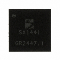
SX1441I077TRLF Semtech, SX1441I077TRLF Datasheet - Page 41

SX1441I077TRLF
Manufacturer Part Number
SX1441I077TRLF
Description
IC SYS-ON-CHIP BLUETOOTH 72LFBGA
Manufacturer
Semtech
Datasheet
1.SX1441EVK.pdf
(85 pages)
Specifications of SX1441I077TRLF
Frequency
2.4GHz
Modulation Or Protocol
Bluetooth v1.2, Class 2
Applications
Bluetooth v1.2
Voltage - Supply
2 V ~ 3.6 V
Current - Receiving
12.5mA
Data Interface
PCB, Surface Mount
Memory Size
4kByte ROM, 40kByte RAM
Antenna Connector
PCB, Surface Mount
Operating Temperature
-40°C ~ 85°C
Package / Case
72-LFBGA
Lead Free Status / RoHS Status
Lead free / RoHS Compliant
Power - Output
-
Sensitivity
-
Data Rate - Maximum
-
Current - Transmitting
-
Other names
SX1441I077LFTR
Personal Area Network
Switching between different modes must be done while the concerned counters are stopped. While switching
capture mode on and off, unwanted interrupts can appear on the interrupt channels concerned by this mode
change.
The Table 71 shows the operation modes for counters C and D as a function of the mode control bits.
3.10.6 Counter / Timer Mode
The counters in counter / timer mode are used to generate interrupts after a predefined number of clock periods
applied on the counter clock input have elapsed.
Each counter can be set individually either in upcount mode by setting bit 4 to 7 in register RegCntConfig1 or in
downcount mode by resetting these bit. Counters A and B can be cascaded to behave as a 16-bit counter by
setting RegCntConfig1[2]. Counters C and D can be also cascaded by setting RegCntConfig1[3]. When
cascaded, the up/down count modes of counters B and D are defined respectively by the up/down count modes set
for the counters A and C.
When in upcount mode, the counter will start incrementing from zero up to the target value which has been written
in the corresponding RegCntX register(s). When the counter content is equal to the target value, an interrupt is
© Semtech 2006
RegCnt-
Config1
[2]
0
1
0
1
0
1
0
1
RegCntConfig1
[3]
0
1
0
1
RegCnt-
Config1
[0]
0
0
1
1
0
0
1
1
[1]
0
0
1
1
Counter 8b
Downup: C
RegCnt-
Config2
Downup: C
Counter C
[5:4]
PWM 8b
1X
X1
1X
X1
1X
X1
1X
X1
00
00
00
00
or
or
or
or
mode
PWM 10 – 16b CD
Counter 16b CD
Downup: C
Downup: C
Table 71 - Counters C&D: operation modes
Table 70 – Counters A&B operation modes
Counter 8b
Downup: A
Captured counter 16b AB
Counter A
Downup: A
Downup: A
Downup: A
counter 8b
Captured 10 – 16b PWM
(captured value on 16b)
Captured
Captured
PWM 8b
PWM 8b
mode
Counter 8b
Downup: D
PWM 10 – 16b AB
Counter 8b
Downup: D
Counter D
Counter 16b AB
mode
Downup: A
Downup: A
Downup: A
Downup A
Counter 8b
Downup: B
Counter 8b
Counter B
Downup: B
Downup: B
Downup: B
counter 8b
counter 8b
Captured
Captured
41
mode
Counter C IRQ
Counter CD
Counter C
source
-
-
Counter A IRQ
Counter AB
Capture AB
Capture AB
Counter A
Capture A
Capture A
source
-
-
Counter D IRQ
Counter D
Counter D
source
SX1441 – Bluetooth® 1.2 SoC
-
-
Capture AB
Capture AB
Counter B
Counter B
Counter B
Capture B
Capture B
source
IRQ
-
-
PWM CD
function
www.semtech.com
PWM C
PB[1]
PB(1)
PB(1)
Data Sheet
PWM AB
PWM AB
function
PWM A
PWM A
PB[0]
PB[0]
PB[0]
PB[0]
PB[0]


