ETRX2 Telegesis Ltd, ETRX2 Datasheet - Page 11
ETRX2
Manufacturer Part Number
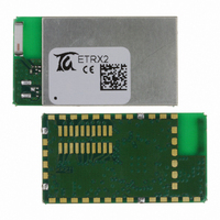
ETRX2
Description
MODULE ZIGBEE EM250 CHIP ANT
Manufacturer
Telegesis Ltd
Specifications of ETRX2
Frequency
2.4GHz
Data Rate - Maximum
250kbps
Modulation Or Protocol
802.15.4 Zigbee
Applications
ISM
Power - Output
3dBm
Sensitivity
-98dBm
Voltage - Supply
2.1 V ~ 3.6 V
Current - Receiving
35.5mA
Current - Transmitting
35.5mA
Data Interface
PCB, Surface Mount
Memory Size
128kB Flash, 5kB SRAM
Antenna Connector
On-Board, Chip
Operating Temperature
-40°C ~ 85°C
Package / Case
Module
Module Applications
AMR, Building Automation, Wireless Sensor Network, M2M Industrial Controls
Mcu Supported Families
EM250
Processor Type
EM250
Wireless Protocol
IEEE 802.15.4
Data Rate
250Kbps
Module Interface
I2C, SPI, UART
Rohs Compliant
Yes
Lead Free Status / RoHS Status
Lead free / RoHS Compliant
Other names
920-1000-2


4 Hardware Description
4.1 Hardware Options
Please contact the manufacturer if any of the options described below could be useful in your
product design. Please note that to include these options a high order quantity is required and
they are not available as standard products.
4.1.1
Although the EM250 already contains an internal LDO regulator, the module can be supplied with
an additional integrated onboard LDO regulator or DC/DC converter. Some applications could
benefit from this additional regulator in instances where:
(1)
(2)
(3)
Two different types of regulators are available, a linear low dropout (LDO) type or a high efficiency
switched buck regulator.
optimum regulator can be selected.
4.1.2
A second option which is available is an on-board 32.768kHz crystal reference. This option can be
provided for applications which require a high precision reference clock.
4.1.3
Thirdly, the RF output can be connected to pad 2 for routing on to the underlying circuit board.
There is then no ceramic antenna nor U.FL connector.
©2009 Telegesis (UK) Ltd
integrated
antenna
pad
U.FL socket
Further extension of the input voltage range is required
Extended battery life is obtained by replacing the regulator within the EM250 with a special
ultra-low quiescent current regulator
Operation is required using very noisy power supplies
On-board DC Regulator
On-board Reference Crystal
RF output pad
VBAT
LDO
or
DC
converter
(optional)
filtering and
selection,
matching
terminal
circuitry
rf
VREG
Depending on the power supply conditions of the application the
BALUN
Figure 2: Hardware Diagram
1,8Vdc
VBAT
LDO
24MHz
- 11 -
RF transceiver 2.4GHz
128kB flash / 5k RAM
RF transceiver 2.4GHz
128kB flash / 5k RAM
16-bit XAP2b µC
16-bit XAP16b uC
EM250
32,768kHz
(optional)
ETRX2 Product Manual (Rev 1.09)
UART
4
RESET
I/O0 – I/O11
A/D
SIF
programming
RESET
I / O
ETRX2
Related parts for ETRX2
Image
Part Number
Description
Manufacturer
Datasheet
Request
R

Part Number:
Description:
KIT DEVELOPMENT FOR ETRX357
Manufacturer:
Telegesis Ltd
Datasheet:

Part Number:
Description:
MODULE ZIGBEE USB STICK
Manufacturer:
Telegesis Ltd
Datasheet:

Part Number:
Description:
MODULE ZIGBEE PWR AMP USB STICK
Manufacturer:
Telegesis Ltd
Datasheet:

Part Number:
Description:
ZIGBEE ETHERNET ACCESS POINT
Manufacturer:
Telegesis Ltd
Datasheet:

Part Number:
Description:
ZIGBEE ETHERNET ACCESS POINT
Manufacturer:
Telegesis Ltd
Datasheet:

Part Number:
Description:
MODULE ZIGBEE EM357 W/CHIP ANT
Manufacturer:
Telegesis Ltd
Datasheet:

Part Number:
Description:
MODULE ZIGBEE W/PWR AMP
Manufacturer:
Telegesis Ltd
Datasheet:
Part Number:
Description:
MODULE ZIGBEE W/PA LNA CHIP ANT
Manufacturer:
Telegesis Ltd
Datasheet:
Part Number:
Description:
MODULE ZIGBEE W/PA LNA U.FL
Manufacturer:
Telegesis Ltd
Datasheet:
Part Number:
Description:
MODULE, ZIGBEE, ETRX351, CHIP ANT
Manufacturer:
Telegesis Ltd
Datasheet:
Part Number:
Description:
MODULE, ZIGBEE, ETRX3, HIROSE
Manufacturer:
Telegesis Ltd
Datasheet:
Part Number:
Description:
MODULE, ZIGBEE, ETRX3, PA+LNA, CHIP
Manufacturer:
Telegesis Ltd
Datasheet:
Part Number:
Description:
MODULE, ZIGBEE, ETRX3, PA+LNA, HIROS
Manufacturer:
Telegesis Ltd
Datasheet:
Part Number:
Description:
MODULE, ZIGBEE, ETRX351, HIROSE
Manufacturer:
Telegesis Ltd
Datasheet:
Part Number:
Description:
MODULE
Manufacturer:
Telegesis Ltd
Datasheet: