RN-24S Roving Networks Inc, RN-24S Datasheet - Page 28
RN-24S
Manufacturer Part Number
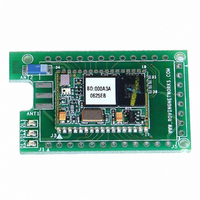
RN-24S
Description
SUPERMODULE BLUETOOTH CHIP ANT
Manufacturer
Roving Networks Inc
Specifications of RN-24S
Frequency
2.4GHz
Data Rate - Maximum
721kbps
Modulation Or Protocol
Bluetooth v2.0+EDR, Class 1 & 2
Applications
Bluetooth v2.0
Power - Output
4dBm
Sensitivity
-80dBm
Voltage - Supply
4 V ~ 24 V
Current - Receiving
40mA
Current - Transmitting
40mA
Data Interface
PCB, Surface Mount
Antenna Connector
On-Board, Chip
Package / Case
Module
Wireless Frequency
2.402 GHz to 2.48 GHz
Interface Type
UART
Data Rate
240 Kbps to 300 Kbps
Modulation
FHSS, GFSK
Operating Voltage
3.3 V
Antenna
Chip Antenna
Board Size
20.32 mm x 50.8 mm x 4.08 mm
Lead Free Status / RoHS Status
Lead free / RoHS Compliant
Operating Temperature
-
Memory Size
-
Lead Free Status / Rohs Status
Lead free / RoHS Compliant
Other names
740-1008


Board PWR
Board GND
RS-232 SERIAL-CN1
SERIAL 3.3V (J1)
PIO-SWITCH-LEDS
6-Pin SPI (J2)
Pin 1 - DCD
Pin 2 - TX
Pin 3 - RX
Pin 4 - DTR
Pin 5 - GND
Pin 6 - DSR
Pin 7 - RTS
Pin 8 - CTS
Pin 9 - RING
PWR
GND
CTS
RTS
TX
RX
PIO#2
PIO#10
PIO#11
PIO#4
PIO#3
PIO#6
PIO#7
PIO#5
PIO#8
MISO
MOSI
SPICK
SPICS
PWR
GND
Signal Name
www.rovingnetworks.com
809 University Avenue
SWITCH-1
SWITCH-2
SWITCH-3
SWITCH-4
Connector
LED-DL1
LED-DL2
LED-DL3
DB9
DB9
DB9
DB9
DB9
DB9
DB9
DB9
DB9
J1-1
J1-2
J1-3
J1-4
J1-5
J1-6
J1-7
J1-8
J1-9
J2-1
J2-2
J2-3
J2-4
J2-5
J2-6
P1
P1
•
Los Gatos, CA 95032
YELLOW
GREEN
PIN #
RED
1
2
2
3
4
5
6
7
8
9
1
2
3
4
5
6
7
8
9
1
2
3
4
~ 28 ~
BT Connection (high state)
Pulses for status 0-3.3Vdc
Auto Discover and Pairing
Reserved programming)
•
Reserved programming)
Reserved programming)
Reserved programming)
Auto Connect as Master
RX, TX data low to high
OUT→ *
IN← *
Baudrate (115K - 9600)
Optional 3.3VDC Power
Reset Default Settings
Power IN (5.0 -9.0 Vdc)
PWR →IN (4.5 -11Vdc)
Tel (408) 395-6539
Software controlled
Optional 5VDC in
OUT→ 0 - 3.3Vdc
OUT→ 0 - 3.3Vdc
Optional Ground
I/O Direction
GROUND
Not used
Not used
Not used
GPIO
GPIO
<—>
<—>
OUT
IN
IN
IN
(active low)
(active low)
rn-bluetooth-um Version 4.77 1/24/2011
Advanced User Manual
• info@RovingNetworks.com
RX char low speed mode
PIO2 – BT connect status
Modem control options
must be removed when
PIO10- remote DTR out
PIO11- remote RTS out
NOTE: the RS232 drive
using the serial 3.3v
signals (see below)
DTR output
RTS output
DCD input
DSR input
CTS input
Related parts for RN-24S
Image
Part Number
Description
Manufacturer
Datasheet
Request
R

Part Number:
Description:
ADAPTER BLUETOOTH FRFLY SRL FEML
Manufacturer:
Roving Networks Inc
Datasheet:

Part Number:
Description:
ADAPTER BLUETOOTH FRFLY SRL MALE
Manufacturer:
Roving Networks Inc
Datasheet:

Part Number:
Description:
ADAPTER BLUETOOTH FIREFLY RS422
Manufacturer:
Roving Networks Inc
Datasheet:

Part Number:
Description:
SUPERMODULE BLUETOOTH SMA JACK
Manufacturer:
Roving Networks Inc
Datasheet:

Part Number:
Description:
MODULE BLUETOOTH V2.1+EDR
Manufacturer:
Roving Networks Inc
Datasheet:

Part Number:
Description:
MODULE BLUETOOTH V2.1+EDR
Manufacturer:
Roving Networks Inc
Datasheet:

Part Number:
Description:
ANTENNA 2.4GHZ 4" SMA MALE
Manufacturer:
Roving Networks Inc
Datasheet:

Part Number:
Description:
ADAPTER BLUETOOTH 2.0 USB
Manufacturer:
Roving Networks Inc
Datasheet:

Part Number:
Description:
ADAPTER BLUETOOTH USB DRIVERLESS
Manufacturer:
Roving Networks Inc
Datasheet:

Part Number:
Description:
MODULE BLUETOOTH V2.0+EDR
Manufacturer:
Roving Networks Inc
Datasheet:

Part Number:
Description:
MODULE BLUETOOTH W/ANT CLASS1
Manufacturer:
Roving Networks Inc
Datasheet:

Part Number:
Description:
MODULE BLUETOOTH 2.0/EDR CLASS1
Manufacturer:
Roving Networks Inc
Datasheet:

Part Number:
Description:
MODULE BLUETOOTH AUDIO V1.2
Manufacturer:
Roving Networks Inc
Datasheet:

Part Number:
Description:
MODULE SOCKET BLUETOOTH CLASS1
Manufacturer:
Roving Networks Inc
Datasheet:
Part Number:
Description:
MODULE BLUETOOTH V2.1+EDR
Manufacturer:
Roving Networks Inc
Datasheet: