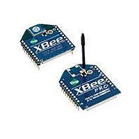
XBP24-ASI-001 Digi International, XBP24-ASI-001 Datasheet - Page 21

XBP24-ASI-001
Manufacturer Part Number
XBP24-ASI-001
Description
MODULE XBEE 1MW W/RPSMA
Manufacturer
Digi International
Series
XBEE-PRO™r
Specifications of XBP24-ASI-001
Frequency
2.4GHz
Data Rate - Maximum
250kbps
Modulation Or Protocol
802.15.4
Applications
Home/Building Automation, Industrial Control, ZigBee™
Power - Output
18dBm
Sensitivity
-100dBm
Voltage - Supply
2.8 V ~ 3.4 V
Current - Receiving
55mA
Current - Transmitting
215mA @ 3.3V
Data Interface
PCB, Through Hole
Antenna Connector
RP-SMA
Operating Temperature
-40°C ~ 85°C
Package / Case
Module
Lead Free Status / RoHS Status
Lead free / RoHS Compliant
Memory Size
-
Lead Free Status / Rohs Status
Lead free / RoHS Compliant
Available stocks
Company
Part Number
Manufacturer
Quantity
Price
Part Number:
XBP24-ASI-001J
Manufacturer:
XBEE
Quantity:
20 000
XBee®/XBee‐PRO® RF Modules ‐ 802.15.4 ‐ v1.xEx [2009.09.23]
Modes of Operation
Idle Mode
Transmit/Receive Modes
RF Data Packets
Direct and Indirect Transmission
XBee®/XBee-PRO® RF Modules operate in five modes.
Figure 2‐07. Modes of Operation
When not receiving or transmitting data, the RF module is in Idle Mode. The module shifts into the
other modes of operation under the following conditions:
Each transmitted data packet contains a Source Address and Destination Address field. The Source
Address matches the address of the transmitting module as specified by the MY (Source Address)
parameter (if MY >= 0xFFFE), the SH (Serial Number High) parameter or the SL (Serial Number
Low) parameter. The <Destination Address> field is created from the DH (Destination Address
High) and DL (Destination Address Low) parameter values. The Source Address and/or Destination
Address fields will either contain a 16-bit short or long 64-bit long address.
The RF data packet structure follows the 802.15.4 specification.
[Refer to the XBee/XBee-PRO Addressing section for more information]
There are two methods to transmit data:
Indirect Transmissions can only occur on a Coordinator. Thus, if all nodes in a network are End
Devices, only Direct Transmissions will occur. Indirect Transmissions are useful to ensure packet
delivery to a sleeping node. The Coordinator currently is able to retain up to 2 indirect messages.
© 2009 Digi Internatonal, Inc.
• Transmit Mode (Serial data is received in the DI Buffer)
• Receive Mode (Valid RF data is received through the antenna)
• Sleep Mode (Sleep Mode condition is met)
• Command Mode (Command Mode Sequence is issued)
• Direct Transmission - data is transmitted immediately to the Destination Address
• Indirect Transmission - A packet is retained for a period of time and is only transmitted after
the destination module (Source Address = Destination Address) requests the data.
21


