XBP24-ASI-001 Digi International, XBP24-ASI-001 Datasheet - Page 36
XBP24-ASI-001
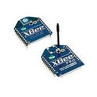
Manufacturer Part Number
XBP24-ASI-001
Description
MODULE XBEE 1MW W/RPSMA
Manufacturer
Digi International
Series
XBEE-PRO™r
Specifications of XBP24-ASI-001
Frequency
2.4GHz
Data Rate - Maximum
250kbps
Modulation Or Protocol
802.15.4
Applications
Home/Building Automation, Industrial Control, ZigBee™
Power - Output
18dBm
Sensitivity
-100dBm
Voltage - Supply
2.8 V ~ 3.4 V
Current - Receiving
55mA
Current - Transmitting
215mA @ 3.3V
Data Interface
PCB, Through Hole
Antenna Connector
RP-SMA
Operating Temperature
-40°C ~ 85°C
Package / Case
Module
Lead Free Status / RoHS Status
Lead free / RoHS Compliant
Memory Size
-
Lead Free Status / Rohs Status
Lead free / RoHS Compliant
Available stocks
Company
Part Number
Manufacturer
Quantity
Price

Part Number:
XBP24-ASI-001J
Manufacturer:
XBEE
Quantity:
20 000


XBee®/XBee‐PRO® RF Modules ‐ 802.15.4 ‐ v1.xEx [2009.09.23]
Command Descriptions
A1 (End Device Association) Command
A2 (Coordinator Association) Command
Command descriptions in this section are listed alphabetically. Command categories are desig-
nated within "< >" symbols that follow each command title. XBee®/XBee-PRO® RF Modules
expect parameter values in hexadecimal (designated by the "0x" prefix).
All modules operating within the same network should contain the same firmware version.
<Networking {Association}> The A1 command is
used to set and read association options for an
End Device.
Use the table below to determine End Device
behavior in relation to the A1 parameter.
<Networking {Association}> The A2 command is
used to set and read association options of the
Coordinator.
Use the table below to determine Coordinator
behavior in relation to the A2 parameter.
The binary equivalent of the default value (0x06) is 00000110. ‘Bit 0’ is the last digit of the sequence.
Bit number
0 - ReassignPanID
1 - ReassignChannel
2 - AutoAssociate
3 - PollCoordOnPinWake
4 - 7
Bit number
0 - ReassignPanID
1 - ReassignChannel
2 - AllowAssociate
3 - 7
© 2009 Digi Internatonal, Inc.
End Device Association Option
0 - Will only associate with Coordinator operating on PAN ID that matches Node Identifier
1 - May associate with Coordinator operating on any PAN ID
0 - Will only associate with Coordinator operating on Channel that matches CH setting
1 - May associate with Coordinator operating on any Channel
0 - Device will not attempt Association
1 - Device attempts Association until success
Note: This bit is used only for Non-Beacon systems. End Devices in a Beaconing system must
always associate to a Coordinator
0 - Pin Wake will not poll the Coordinator for pending (indirect) Data
1 - Pin Wake will send Poll Request to Coordinator to extract any pending data
[reserved]
End Device Association Option
0 - Coordinator will not perform Active Scan to locate available PAN ID. It will operate on ID
(PAN ID).
1 - Coordinator will perform Active Scan to determine an available ID (PAN ID). If a PAN ID
conflict is found, the ID parameter will change.
0 - Coordinator will not perform Energy Scan to determine free channel. It will operate on the
channel determined by the CH parameter.
1 - Coordinator will perform Energy Scan to find a free channel, then operate on that channel.
0 - Coordinator will not allow any devices to associate to it.
1 - Coordinator will allow devices to associate to it.
[reserved]
AT Command: ATA1
Parameter Range: 0 - 0x0F [bitfield]
Default Parameter Value: 0
Related Commands: ID (PAN ID), NI (Node
Identifier), CH (Channel), CE (Coordinator
Enable), A2 (Coordinator Association)
Minimum Firmware Version Required: v1.x80
AT Command: ATA2
Parameter Range: 0 - 7 [bitfield]
Default Parameter Value: 0
Related Commands: ID (PAN ID), NI (Node
Identifier), CH (Channel), CE (Coordinator
Enable), A1 (End Device Association), AS
Active Scan), ED (Energy Scan)
Minimum Firmware Version Required: v1.x80
36
Related parts for XBP24-ASI-001
Image
Part Number
Description
Manufacturer
Datasheet
Request
R

Part Number:
Description:
MODULE 802.15.4 100MW CHIP ANT
Manufacturer:
Digi International/Maxstream
Datasheet:
Part Number:
Description:
MODULE 802.15.4 RS-232 ANT
Manufacturer:
Digi International/Maxstream
Datasheet:
Part Number:
Description:
MODULE XBEE PRO ZNET 2.5 W/RPSMA
Manufacturer:
Digi International/Maxstream
Datasheet:
Part Number:
Description:
KIT STARTER XBEE PRO
Manufacturer:
Digi International/Maxstream
Datasheet:
Part Number:
Description:
MODULE 802.15.4 100MW WIRE ANT
Manufacturer:
Digi International/Maxstream
Datasheet:
Part Number:
Description:
MODULE 802.15.4 100MW U.FL CON
Manufacturer:
Digi International/Maxstream
Datasheet:
Part Number:
Description:
MODULE XBEE PRO ZNET 2.5 W/CHIP
Manufacturer:
Digi International/Maxstream
Datasheet:
Part Number:
Description:
MODULE XBEE PRO ZNET 2.5 W/WHIP
Manufacturer:
Digi International/Maxstream
Datasheet:

Part Number:
Description:
MODULE ZIGBEE-PRO W/WIRED ANT
Manufacturer:
Digi International
Datasheet:
Part Number:
Description:
MODULE ZIGBEE-PRO W/RPSMA ANT
Manufacturer:
Digi International
Datasheet:
Part Number:
Description:
IC ARM MICROPROCESSOR 177BGA
Manufacturer:
Digi International
Datasheet:
Part Number:
Description:
DIGI CONNECT 4MB FLASH 8MB RAM
Manufacturer:
Digi International
Datasheet:

Part Number:
Description:
ME 8MB SDRAM 2MB FLASH SINGLE
Manufacturer:
Digi International
Datasheet:
Part Number:
Description:
ME 8MB SDRAM 2MB FLASH SINGLE
Manufacturer:
Digi International
Datasheet:

Part Number:
Description:
MODULE 9P 8MB SDRAM 4MB FLASH
Manufacturer:
Digi International/Maxstream
Datasheet: