DM2200-434VM RFM, DM2200-434VM Datasheet - Page 4
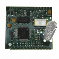
DM2200-434VM
Manufacturer Part Number
DM2200-434VM
Description
433.92 MHZ, 10 MW MESH MODULE, S
Manufacturer
RFM
Series
DM2200r
Datasheet
1.DM2200-434VM.pdf
(6 pages)
Specifications of DM2200-434VM
Frequency
433.92MHz
Data Rate - Maximum
9.6kbps
Modulation Or Protocol
OOK
Applications
Wireless Mesh Networks
Power - Output
10dBm
Voltage - Supply
2.9 V ~ 3.6 V
Current - Receiving
6mA
Current - Transmitting
36mA
Data Interface
Pads for Pins
Antenna Connector
On-Board, Spring
Operating Temperature
-40°C ~ 85°C
Package / Case
Module
Lead Free Status / RoHS Status
Lead free / RoHS Compliant
Sensitivity
-
Memory Size
-
Lead Free Status / Rohs Status
Lead free / RoHS Compliant
Other names
583-1040


Pin Descriptions
www.RFM.com E-mail: info@rfm.com
©2008 by RF Monolithics, Inc.
J1-10
J1-11
J1-12
J1-13
J1-14
J2-10
J2-11
J2-12
J2-13
J2-14
J1-1
J1-2
J1-3
J1-4
J1-5
J1-6
J1-7
J1-8
J1-9
J2-1
J2-2
J2-3
J2-4
J2-5
J2-6
J2-7
J2-8
J2-9
Pin
GP0/RSSI
VREN
Name
CFG0
CFG1
CFG2
CFG3
GND
TWS
GND
GND
GND
VDD
TCK
RST
RXD
TXD
CTS
RTS
GP1
GP2
GP3
GP4
GP5
GP6
GP7
TD0
VIN
TDI
This pin is connected to ground.
This pin is the input to the DM2200 on-board voltage regulator. The minimum input voltage to this pin is 3.3 V,
and the maximum input to this pin is 14.0 V.
This pin is the enable input for the DM2200 on-board regulator. To enable the on-board regulator, connect this
pin to J1-2. To disable the on-board regulator, connect this pin to ground.
This pin is connected to the DM2200 positive power supply buss. When the module is powered from the
on-board regulator, this pin can provide up to 5 mA of current at 3.0 Vdc. Note this current adds to the receive,
transmit and sleep currents listed in the specifications on Page 1. The external load must not impress more
than 10 mV peak -peak ripple on the supply buss. If the on-board regulator is disabled, the module can be pow-
ered through this pin by an external 2.9 to 3.7 Vdc source (maximum ripple 10 mV peak-peak).
This pin is only used for factory programming. It must be left unconnected in normal operation.
This pin is only used for factory programming. It must be left unconnected in normal operation.
This pin is only used for factory programming. It must be left unconnected in normal operation.
This pin is only used for factory programming. It must be left unconnected in normal operation.
This pin is only used for factory programming. It must be left unconnected in normal operation (reset is CFG3).
This pin is an auxiliary digital I/O pin. The default configuration of this pin is a digital output.
This pin is an auxiliary digital I/O pin. The default configuration of this pin is a digital output.
This pin is an auxiliary digital I/O pin. The default configuration of this pin is a digital output.
This pin is a software reset pin. Logic high is normal operation. Logic low invokes software resets.
This pin is connected to ground.
This pin is connected to ground.
This pin is the serial data input (CMOS).
This pin is the serial data output (CMOS).
This pin is a serial data flow control input (CMOS).
This pin is a serial data flow control output (CMOS).
This pin is an I/O pin dedicated to monitoring the RSSI circuit output. It is configured as an analog-to-digital
converter input. The RSSI signal can also be monitored externally at this pin.
This pin is an I/O pin. The default configuration of this pin is a digital input with optional pulse counting capabil-
ity. A 24-bit register is maintained within the DM2200 to accumulate pulse counts. This input can count up to
10 pulses/second. This input supports interrupts, allowing pulse counting or alarm monitoring while the DM2200
is operating in a low current “sleep” mode.
This pin is an I/O pin. The default configuration of this pin is a digital input. This input supports interrupts, allow-
ing alarm monitoring while the DM2200 is operating in a low current “sleep” mode.
This pin is an I/O pin. The default configuration of this pin is a digital input.
This pin is an I/O pin. The default configuration of this pin is a digital output.
This pin is an I/O pin. The default configuration of this pin is a digital output.
This pin is an I/O pin. The default configuration of this pin is an analog-to-digital converter input.
This pin is an I/O pin. The default configuration of this pin is an analog-to-digital converter input.
This pin is connected to ground.
Description
DM2200-434VM - 4/18/08
Page 4 of 6
Related parts for DM2200-434VM
Image
Part Number
Description
Manufacturer
Datasheet
Request
R

Part Number:
Description:
DM2200 433.92 MHZ DEVELOPMENT KI
Manufacturer:
RFM
Datasheet:
Part Number:
Description:
DM2200 916.5 MHZ DEVELOPMENT KIT
Manufacturer:
RFM
Datasheet:

Part Number:
Description:
916.5 MHZ, 10 MW MESH MODULE, SE
Manufacturer:
RFM
Datasheet:

Part Number:
Description:
916.5 MHZ, 10 MW MESH MODULE, SE
Manufacturer:
RFM
Datasheet:

Part Number:
Description:
ASH RX 115.2 KBPS 433.92 MHZ
Manufacturer:
RFM
Datasheet:

Part Number:
Description:
RFIC TRANCEIVER MULTI-CHANNEL FS
Manufacturer:
RFM
Datasheet:

Part Number:
Description:
ASH TX 115.2 KBPS 433.92 MHZ
Manufacturer:
RFM
Datasheet:
Part Number:
Description:
Filters 1602MHz BW=61MHz
Manufacturer:
RFM
Datasheet:

Part Number:
Description:
RESONATOR, SM3030-6
Manufacturer:
RFM
Datasheet:

Part Number:
Description:
RESONATOR, SM3030-6
Manufacturer:
RFM
Datasheet:

Part Number:
Description:
10-Terminal Ceramic Surface-Mount Case 7 x 5 mm Nominal Footprint
Manufacturer:
RFM [RF Monolithics, Inc]
Datasheet:
Part Number:
Description:
QUAD-BAND GSM850/GSM/DCS/PCS POWER AMP MODULE
Manufacturer:
RFM [RF Monolithics, Inc]
Datasheet:
Part Number:
Description:
402 to 405 MHz Medical Band Front-end Filter
Manufacturer:
RFM [RF Monolithics, Inc]
Datasheet:
Part Number:
Description:
674.03 MHz SAW Resonator
Manufacturer:
RFM [RF Monolithics, Inc]
Datasheet: