ATAB5276 Atmel, ATAB5276 Datasheet - Page 4
ATAB5276
Manufacturer Part Number
ATAB5276
Description
BOARD DEV ANT DRVR TPM ATA5276
Manufacturer
Atmel
Series
SmartRF®r
Type
LF Antenna Driverr
Specifications of ATAB5276
Contents
Board
For Use With/related Products
ATA5276
Lead Free Status / RoHS Status
Lead free / RoHS Compliant


4.2
4
Typical Parameters of Antenna Module
ATAK5276-83
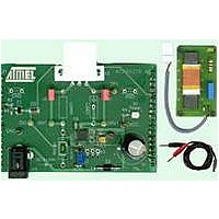
Figure 4-2.
The transmitter board (see
communicating with a host PC. Operation software must be installed on the host via the
enclosed CD-ROM. A power source of typically 12V/2A is used to supply the microcontroller
base board and the transmitter board in parallel with separate connectors as seen in
on page
antenna in use. An external antenna module (see
voltage capacitor and resistor matching the resonant frequency and Q-factor. The capacitor
CANT (C1) is used to match the resonant frequency to fres = 125 kHz ±3 kHz, and the resistor
RANT (R1) sets the Q-factor to about 25. With the default module adjustment, a current flow of
around 0.6 Ap at VBATT = 12V can be achieved. Therefore, jumper J3 has to be closed
(R
decreased leading to a regulation level of typically 0.37 Ap.
To reach the maximum antenna current (1.5 Ap), the series resistor RANT (R1) on the antenna
module has to be shorted and the current regulation set point has to be set to maximum
R
Optionally, RANT and CANT can be placed on the board if a customized pure antenna coil will
be used. Then, Jumpers J1 and J2 have to be opened.
Note:
Coil Inductance:
Coil Resistance:
Impedance:
Module Series Resistor:
Series Capacitor:
Total Q-Factor:
CR
CR
= R
= R
CR1
The power dissipation of shunt resistor RSEN and module resistor RANT must be considered if a
high antenna current in continuous operation mode will be programmed.
CR1
1. The antenna driver frequency is tracked according to the resonant condition of the
//R
//R
CR2
Antenna Module
CR2
= 25 (J3 closed).
= 25 k ). If Jumper J3 is open (R
Figure 4-1 on page
L
R
Z
RANT (R1) = 10 [ ]
4.7 nF/1400V
Q
125
125
125
125
= 345 [µH] ±5%
= 2.5 [ ]
= 271 [ ]
= 22
3) is patched onto a microcontroller base board
Figure 4-2 on page
CR
= R
CR1
= 100 k ) the current set point is
4) is used, with the high
4857C–AUTO–07/06
Figure 2-1
Related parts for ATAB5276
Image
Part Number
Description
Manufacturer
Datasheet
Request
R

Part Number:
Description:
DEV KIT FOR AVR/AVR32
Manufacturer:
Atmel
Datasheet:

Part Number:
Description:
INTERVAL AND WIPE/WASH WIPER CONTROL IC WITH DELAY
Manufacturer:
ATMEL Corporation
Datasheet:
Part Number:
Description:
Low-Voltage Voice-Switched IC for Hands-Free Operation
Manufacturer:
ATMEL Corporation
Datasheet:
Part Number:
Description:
MONOLITHIC INTEGRATED FEATUREPHONE CIRCUIT
Manufacturer:
ATMEL Corporation
Datasheet:
Part Number:
Description:
AM-FM Receiver IC U4255BM-M
Manufacturer:
ATMEL Corporation
Datasheet:
Part Number:
Description:
Monolithic Integrated Feature Phone Circuit
Manufacturer:
ATMEL Corporation
Datasheet:
Part Number:
Description:
Multistandard Video-IF and Quasi Parallel Sound Processing
Manufacturer:
ATMEL Corporation
Datasheet:
Part Number:
Description:
High-performance EE PLD
Manufacturer:
ATMEL Corporation
Datasheet:
Part Number:
Description:
8-bit Flash Microcontroller
Manufacturer:
ATMEL Corporation
Datasheet:
Part Number:
Description:
2-Wire Serial EEPROM
Manufacturer:
ATMEL Corporation
Datasheet: