STGIPS10K60A STMicroelectronics, STGIPS10K60A Datasheet - Page 16
STGIPS10K60A
Manufacturer Part Number
STGIPS10K60A
Description
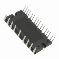
MOD IPM 600V 10A 25-SDIP
Manufacturer
STMicroelectronics
Type
IGBTr
Specifications of STGIPS10K60A
Configuration
3 Phase
Current
10A
Voltage
600V
Voltage - Isolation
2500VDC
Package / Case
PCB Module
Module Configuration
3-Phase Bridge
Transistor Polarity
N Channel
Dc Collector Current
10A
Collector Emitter Voltage Vces
600V
Power Dissipation Pd
33W
Operating Temperature Range
-40°C To
Rohs Compliant
Yes
Collector-emitter Saturation Voltage
2.1 V
Continuous Collector Current At 25 C
10 A
Power Dissipation
26 W
Maximum Operating Temperature
+ 125 C
Minimum Operating Temperature
- 40 C
Mounting Style
Through Hole
Operating Temperature (max)
125C
Operating Temperature (min)
-40C
Pin Count
25
Mounting
Through Hole
Screening Level
Automotive
For Use With
497-10836 - POWER BOARD STGIPS10K60A
Lead Free Status / RoHS Status
Lead free / RoHS Compliant
Other names
497-10404-5
Available stocks
Company
Part Number
Manufacturer
Quantity
Price

Part Number:
STGIPS10K60A
Manufacturer:
ST
Quantity:
20 000


Revision history
6
16/17
Revision history
Table 14.
11-May-2009
15-Jun-2010
16-Apr-2009
06-Apr-2010
17-Jul-2009
Date
Document revision history
Revision
1
2
3
4
5
Doc ID 15587 Rev 5
Initial release.
Added
Reduced V
Document promoted from preliminary data to datasheet.
Inserted
Recommended operating
Updated
Inverter
Figure 6: Maximum IC(RMS) current vs. switching
Figure 7: Maximum IC(RMS) current vs. fSINE (1)
Section 5: Package mechanical
Updated
Minor text changes to improve readability.
Figure 6
part,
Figure 3: Switching time test circuit
Table 5: Total
Table 7: Inverter
CE(sat)
Figure 5: Typical NTC resistance vs
and
value on
Figure
system,
conditions.
part.
Changes
Table
7.
Table 6: Thermal
data.
7.
and
STGIPS10K60A
Table 12:
data,
temperature,
frequency,
and
Table 7:
Related parts for STGIPS10K60A
Image
Part Number
Description
Manufacturer
Datasheet
Request
R

Part Number:
Description:
STMicroelectronics [RIPPLE-CARRY BINARY COUNTER/DIVIDERS]
Manufacturer:
STMicroelectronics
Datasheet:
Part Number:
Description:
STMicroelectronics [LIQUID-CRYSTAL DISPLAY DRIVERS]
Manufacturer:
STMicroelectronics
Datasheet:

Part Number:
Description:
BOARD EVAL FOR MEMS SENSORS
Manufacturer:
STMicroelectronics
Datasheet:
Part Number:
Description:
NPN TRANSISTOR POWER MODULE
Manufacturer:
STMicroelectronics
Datasheet:
Part Number:
Description:
TURBOSWITCH ULTRA-FAST HIGH VOLTAGE DIODE
Manufacturer:
STMicroelectronics
Datasheet:
Part Number:
Description:
Manufacturer:
STMicroelectronics
Datasheet:
Part Number:
Description:
DIODE / SCR MODULE
Manufacturer:
STMicroelectronics
Datasheet:
Part Number:
Description:
DIODE / SCR MODULE
Manufacturer:
STMicroelectronics
Datasheet:
Part Number:
Description:
Search -----> STE16N100
Manufacturer:
STMicroelectronics
Datasheet:
Part Number:
Description:
Search ---> STE53NA50
Manufacturer:
STMicroelectronics
Datasheet:
Part Number:
Description:
NPN Transistor Power Module
Manufacturer:
STMicroelectronics
Datasheet:
Part Number:
Description:
DIODE / SCR MODULE
Manufacturer:
STMicroelectronics
Datasheet: