E3S-CT11 Omron, E3S-CT11 Datasheet - Page 6
E3S-CT11
Manufacturer Part Number
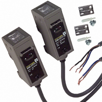
E3S-CT11
Description
SENSOR PHOTO HORZ 98' THRUBEAM
Manufacturer
Omron
Series
E3S-Cr
Type
Long Range Metal Body Sensorr
Specifications of E3S-CT11
Sensing Distance
1181.102" (30m)
Sensing Method
Through-Beam
Output Configuration
PNP - Dark-ON/Light-ON - Selectable
Mounting Type
Bracket Mount, Horizontal
Current - Supply
50mA
Voltage - Supply
10 V ~ 30 V
Response Time
1ms
Package / Case
Module, Pre-Wired
Features
Mutual interference protection
Height
29.5 mm
Length
50 mm
Maximum Operating Temperature
+ 55 C
Minimum Operating Temperature
- 25 C
Operating Supply Voltage
10 V to 30 V
Width
40.4 mm
Light Source
Infrared LED
Connection
Prewired Cable
Output Current
100mA
Supply Voltage Range Dc
10V To 30V
Sensor Housing
Rectangular
Sensor Input
Optical
Sensing Range Max
30m
Switch Terminals
Wire Leaded
Lead Free Status / RoHS Status
Contains lead / RoHS compliant by exemption
Lead Free Status / RoHS Status
Lead free / RoHS Compliant, Contains lead / RoHS compliant by exemption
Other names
E3SCT11
Z1102
Z1102
Available stocks
Company
Part Number
Manufacturer
Quantity
Price
Company:

Part Number:
E3S-CT11
Manufacturer:
OMRON
Quantity:
264
Company:
Part Number:
E3S-CT11-D
Manufacturer:
OMRON
Quantity:
475
Company:
Part Number:
E3S-CT11-L
Manufacturer:
XG
Quantity:
11 700


Nomenclature
Horizontal Model
Safety Precautions
Refer to Warranty and Limitations of Liability.
This product is not designed or rated for ensuring
safety of persons either directly or indirectly.
Do not use it for such purposes.
Do not use the product in atmospheres or environments that exceed
product ratings.
Fuzzy Mutual Interference Prevention Function
If Reflective Sensors are installed side by side, each Sensor may be
influenced by the light emitted from the other Sensors.
The fuzzy mutual interference prevention function of the E3S-C
enables the E3S-C to monitor any light interference for a certain
period before the E3S-C starts emitting light so that the E3S-C can
retrieve the intensity and frequency of the light interference as data.
Using this data, the E3S-C estimates with fuzzy inference the risk of
the malfunctioning of the E3S-C and controls the timing of the E3S-
C’s light emission.
When the risk is low:
The E3S-C waits until there is no light interference and emits light.
When the risk is high:
The E3S-C emits light between each period of light interference.
Cable
Mounting
Output selector *1
The E3S-C uses an oil-resistive cable to ensure oil resistivity.
Do not allow the cable to be bent to a radius of less than 25 mm.
When mounting the E3S-C, do not hit the E3S-C with a hammer, or
the E3S-C will loose watertightness.
Use M4 screws to mount the E3S-C. The tightening torque of each
screw must be 1.18 N·m maximum.
Designing
Wiring
Mounting
indicator
Stability
(green)
Emission
pattern
Emission
pattern
Light
interference
Light
interference
Precautions for Correct Use
S
Min
E3S-CD12
WARNING
SENS
PNP
NPN
D·ON
L·ON
Max
L
Operation panel
cover
Light
indicator
(red)
Sensitivity
adjuster
Operation
selector *2
Model number
Vertical Model
Note: The sensitivity adjuster on Through-beam and Retro-reflective Models is
*1. Use the output selector to select the type of output transistor, NPN or PNP.
*2. Use the operation selector to select the operation mode.
Mounting Bracket
Direct Mounting
Mount the E3S-C as shown in the following illustration.
Mounting with M4 Screws
Mounting with M3 Screws
Optical Axis Adjustment
Optical Lock Holes
By inserting screws into the
optical axis lock holes, the
Mounting Bracket will be in the
direction of the optical axis of the
E3S-C.
Stability indicator
Output selector *1
Operation
selector *2
When mounting the E3S-C with the mounting bracket so that
sensing objects will be in the direction of the mechanical axis, use
the optical axis lock holes.
If it is not possible to mount the E3S-C so that the sensing objects
will be in the direction the mechanical axis, move the E3S-C
upwards, downwards, to the left, or to the right and secure the E3S-
C in the center of the range where the light indicator will be lit, at
which time make sure that the stability indicator is lit.
different.
(green)
S
PNP
NPN
D
ON
L
ON
M4
Optical
axis
Min
L
SENS
Mounting axis
Max
Light indicator
(red)
Operation panel
cover
Sensitivity
adjuster
Two, M3
M4 hole
Two, 4.5 dia.
through holes
M4 hole
E3S-C
M4 hole
Four optical
axis lock
holes (M4)
M3
M4 hole
6
Related parts for E3S-CT11
Image
Part Number
Description
Manufacturer
Datasheet
Request
R

Part Number:
Description:
SENSOR PHOTO VERT 98' THRUBEAM
Manufacturer:
Omron
Datasheet:

Part Number:
Description:
HOR, T-BEAM 30M CONN.
Manufacturer:
Omron
Datasheet:
Part Number:
Description:
VERTICAL, T-BEAM 30M CONN.
Manufacturer:
Omron
Datasheet:
Part Number:
Description:
Industrial Photoelectric Sensors DIFFUSE REFLECTIVE
Manufacturer:
Omron
Datasheet:

Part Number:
Description:
Industrial Photoelectric Sensors POLAR RETROREFLECTIV
Manufacturer:
Omron
Datasheet:
Part Number:
Description:
Photoelectric Sensor
Manufacturer:
Omron
Datasheet:
Part Number:
Description:
Photoelectric Sensor
Manufacturer:
Omron
Datasheet:
Part Number:
Description:
Photoelectric Sensors - Industrial DIFFUSE REFLECTIVE
Manufacturer:
Omron
Datasheet:

Part Number:
Description:
Photoelectric Sensors - Industrial PHOTOELECTRIC SENSOR NC/NR
Manufacturer:
Omron

Part Number:
Description:
Photoelectric Sensors - Industrial 2M DIFFUSE NPN/PNP VERT
Manufacturer:
Omron
Datasheet:


Part Number:
Description:
G6S-2GLow Signal Relay
Manufacturer:
Omron Corporation
Datasheet:
Part Number:
Description:
Compact, Low-cost, SSR Switching 5 to 20 A
Manufacturer:
Omron Corporation
Datasheet:
Part Number:
Description:
Manufacturer:
Omron Corporation
Datasheet: