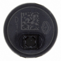
SCP1000-D11 VTI Technologies, SCP1000-D11 Datasheet - Page 10

SCP1000-D11
Manufacturer Part Number
SCP1000-D11
Description
SENSOR I2C 30-120KPA
Manufacturer
VTI Technologies
Series
SCP1000r
Datasheet
1.SCP1000_PCB3.pdf
(37 pages)
Specifications of SCP1000-D11
Pressure Type
Absolute
Operating Pressure
4.35 ~ 17.40 PSI, 30 ~ 120 kPa
Output
Digital
Voltage - Supply
2.4 V ~ 3.3 V
Termination Style
Surface Mount
Operating Temperature
-20°C ~ 70°C
Package / Case
PCB Mount
Lead Free Status / RoHS Status
Lead free / RoHS Compliant
Other names
551-1043-2
Available stocks
Company
Part Number
Manufacturer
Quantity
Price
Company:
Part Number:
SCP1000-D11
Manufacturer:
ST
Quantity:
1 001
Part Number:
SCP1000-D11
Manufacturer:
VTI
Quantity:
20 000
2.2.1.2
2.2.2
VTI Technologies Oy
www.vti.fi
Measurement mode selection
Triggered (low power) measurement mode
If, for some reason, the real time requirement is not met, the output data will be overwritten and an
RTERR error bit is set to ‘1’ in the STATUS register. In order to clear the error status, the host
processor has to read the output pressure data (this data can be invalid). Once the error has been
cleared, normal operation can be continued.
In triggered measurement mode (low power) SCP1000 stays in standby mode until measurement
is externally triggered, see section for more 2.2.4.4 details. The availability of updated pressure and
temperature data is signaled as in continuous measurement modes (through the assertion of the
DRDY pin and a DRDY bit is set to ‘1’ in the STATUS register).
In Figure 5 is presented the timing diagram in the low power measurement mode (triggered).
Figure 5. Timing diagram in triggered measurement mode.
See section 2.2.1.1 for details of clearing the DRDY signal and avoiding real time error.
The DRDY interrupt request has to be cleared before the next trigger signal is applied (rising edge
at TRIG pin Figure 5).
The selection and activation of the measurement mode is done by writing the corresponding mode
activation code (see Table 2) in to OPERATION register, see section 3.2 for register details. The
measurement mode selection and activation is illustrated in Figure 6 below.
DRDY pin
TRIG pin
SCP1000
Interface
Activity
Update
Output
Status
Standby
Measurement and computation
TEMP
UPDATE
Doc.Nr. 8260800.08
Subject to changes
PRESSURE
UPDATE
STANDBY
SCP1000 Series
Rev.0.08
10/37


