A16-1NGN Omron, A16-1NGN Datasheet - Page 200
A16-1NGN
Manufacturer Part Number
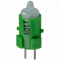
A16-1NGN
Description
NEON LAMP 110V GREEN FOR A16
Manufacturer
Omron
Type
Neon Lamp, 110 VoltsACr
Series
A16r
Datasheets
1.M2DA-7001.pdf
(265 pages)
2.A16-1NRN.pdf
(30 pages)
3.A16-2.pdf
(27 pages)
4.A165-CAA.pdf
(17 pages)
Specifications of A16-1NGN
Accessory Type
Neon Lamp Replacement
Supply Voltage
110V
Base Type
Bi-Pin
Colour
Green
Current Rating
1.5mA
Svhc
No SVHC (15-Dec-2010)
Illumination Colour
Green
Operating Lifetime
10000h
Voltage Rating Vac
110V
Average Bulb Lif
RoHS Compliant
Color
Green
Illumination
Illuminated
Height
13 mm
Illumination Color
Green
Mounting Style
Snap In
Termination Style
Tabs
Lamp Base Type
Bi-Pin
Rohs Compliant
Yes
Average Bulb Life
10000h
Lead Free Status / RoHS Status
Lead free / RoHS Compliant
For Use With/related Products
A16 Series
For Use With
Z1396 - SWTCH KNOB RND 3POS DPDT ILL GRNZ1393 - SWTCH KNOB RND 2POS SPDT ILL GRNZ1390 - SWTCH KNOB RND 2POS SPDT ILL GRNZ1384 - SWITCH KNB RECT 3POS DPDT ILLZ1381 - SWITCH KNB RECT 2POS SPDT ILLZ1378 - SWITCH KNB RECT 2POS SPDT ILLZ1372 - SWITCH KNOB SQ 3-POS DPDT ILLZ1369 - SWITCH KNOB SQ 2-POS SPDT ILLZ1366 - SWITCH KNOB SQ 2-POS SPDT ILLZ1308 - SWITCH PB RND MOM DPDT ILLUM GRNZ1304 - SWITCH PB RECT MOM DPDT ILLUMZ1300 - SWITCH PB SQ MOM DPDT ILLUM GRN
Lead Free Status / Rohs Status
Lead free / RoHS Compliant
Other names
A161NGN
Z1343
Z1343


1. When the panel cutout dimension is 25 dia., remove the supplied
2. When the panel cutout dimension is 30 dia., the A22Z-A30
Matrix Mounting
1. The following diagram provides the dimensions for mounting indi-
198
rubber washer and mount the 25-dia. Ring as shown below.
(Since the A22Z-R25 is not attached to the main body, order sep-
arately.)
Attachment is not attached to the main body, order separately.
vidual Switches, Legend Plates, and Lock Rings with leads con-
nected directly to Switch terminals.
Hold here
Lock Ring
Panel
Mounting nut
Rubber washer
Panel
Lock Ring
22.3 dia.
22.3 dia.
22 dia.
25 dia.
25 dia.
30
Mounting nut
25-dia. Ring
Rubber washer
(mounted to Operation Unit)
30-dia. Resin Attachment
(A22Z-A30)
Operation Unit
Operation Unit
Rubber washer (included)
Mounting Ring
Lock Ring
Mounting panel
(A22Z-R25)
A
Pro-
jecting
part
Panel
Lock Ring
2. The following diagram provides the dimensions for mounting
Dimensions A and B between mounting hole centers are given in the
following tables.
For 1., Above
For 2., Above
Note: 1. The above dimensions are the minimum dimensions when
Mounting the Switch on the Operation
Unit
Insert the Operation Unit into the Switch Unit, aligning the arrow
mark inscribed on the Case with the lever on the Switch Blocks, then
move the lever in the direction indicated by the arrow in the following
figure.
Removing the Switch
A22-10, A22-10S, A22-01, A22-01S
A22-20, A22-20S, A-22-02, A22-02S, A22-11, A22-11S
Naked crimp ter-
minals
Crimp terminals
with insulating
sheaths
Type of crimp
Large Legend Plates with crimp terminals connected to Switch
terminals.
terminal
2. When using pushbuttons exceeding 30 mm, adjust dimen-
using the applicable wiring materials listed on page 201. If
any other materials are used, check the suitability of dimen-
sions in advance.
sion A or B accordingly. (When mounting the A22-M@ in a
matrix, “30 mm” would have to be increased to 40 mm.
A22-10, A22-10S, A22-01, A22-01S 51 mm min.
A22-20, A22-20S, A22-02, A22-02S,
A22-11, A22-11S
A22-10, A22-10S, A22-01, A22-01S 60 mm min.
A22-20, A22-20S, A22-02, A22-02S,
A22-11, A22-11S
Switch model
Switch model
30
Operation Unit
B
Arrow mark
61 mm min.
70 mm min.
45 mm min.
55 mm min.
Dimension B
Dimension A
Lever
Related parts for A16-1NGN
Image
Part Number
Description
Manufacturer
Datasheet
Request
R

Part Number:
Description:
SWITCH PB SQUARE MOM SPDT GREEN
Manufacturer:
Omron
Datasheet:

Part Number:
Description:
SWITCH PB SQUARE MOM SPDT WHITE
Manufacturer:
Omron
Datasheet:
Part Number:
Description:
SWITCH PB SQUARE MOM SPDT YELLOW
Manufacturer:
Omron
Datasheet:
Part Number:
Description:
SWITCH PB RECTANG MOM SPDT BLUE
Manufacturer:
Omron
Datasheet:
Part Number:
Description:
SWITCH PB RECTANG MOM SPDT YEL
Manufacturer:
Omron
Datasheet:
Part Number:
Description:
SWITCH PB SQUARE MOM SPDT BLUE
Manufacturer:
Omron
Datasheet:
Part Number:
Description:
SWITCH PB SQUARE MOM SPDT RED
Manufacturer:
Omron
Datasheet:
Part Number:
Description:
SWITCH PB RECTANG MOM SPDT GREEN
Manufacturer:
Omron
Datasheet:
Part Number:
Description:
SWITCH PB RECTANG MOM SPDT RED
Manufacturer:
Omron
Datasheet:

Part Number:
Description:
SWITCH PB RECTANG MOM SPDT WHITE
Manufacturer:
Omron
Datasheet:
Part Number:
Description:
SWITCH PB ROUND MOM SPDT BLUE
Manufacturer:
Omron
Datasheet:
Part Number:
Description:
SWITCH PB ROUND MOM SPDT GREEN
Manufacturer:
Omron
Datasheet:
Part Number:
Description:
SWITCH PB ROUND MOM SPDT RED
Manufacturer:
Omron
Datasheet:
Part Number:
Description:
SWITCH PB ROUND MOM SPDT WHITE
Manufacturer:
Omron
Datasheet:
Part Number:
Description:
SWITCH PB ROUND MOM SPDT YELLOW
Manufacturer:
Omron
Datasheet: