A16-1NGN Omron, A16-1NGN Datasheet - Page 80
A16-1NGN
Manufacturer Part Number
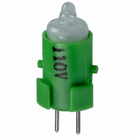
A16-1NGN
Description
NEON LAMP 110V GREEN FOR A16
Manufacturer
Omron
Type
Neon Lamp, 110 VoltsACr
Series
A16r
Datasheets
1.M2DA-7001.pdf
(265 pages)
2.A16-1NRN.pdf
(30 pages)
3.A16-2.pdf
(27 pages)
4.A165-CAA.pdf
(17 pages)
Specifications of A16-1NGN
Accessory Type
Neon Lamp Replacement
Supply Voltage
110V
Base Type
Bi-Pin
Colour
Green
Current Rating
1.5mA
Svhc
No SVHC (15-Dec-2010)
Illumination Colour
Green
Operating Lifetime
10000h
Voltage Rating Vac
110V
Average Bulb Lif
RoHS Compliant
Color
Green
Illumination
Illuminated
Height
13 mm
Illumination Color
Green
Mounting Style
Snap In
Termination Style
Tabs
Lamp Base Type
Bi-Pin
Rohs Compliant
Yes
Average Bulb Life
10000h
Lead Free Status / RoHS Status
Lead free / RoHS Compliant
For Use With/related Products
A16 Series
For Use With
Z1396 - SWTCH KNOB RND 3POS DPDT ILL GRNZ1393 - SWTCH KNOB RND 2POS SPDT ILL GRNZ1390 - SWTCH KNOB RND 2POS SPDT ILL GRNZ1384 - SWITCH KNB RECT 3POS DPDT ILLZ1381 - SWITCH KNB RECT 2POS SPDT ILLZ1378 - SWITCH KNB RECT 2POS SPDT ILLZ1372 - SWITCH KNOB SQ 3-POS DPDT ILLZ1369 - SWITCH KNOB SQ 2-POS SPDT ILLZ1366 - SWITCH KNOB SQ 2-POS SPDT ILLZ1308 - SWITCH PB RND MOM DPDT ILLUM GRNZ1304 - SWITCH PB RECT MOM DPDT ILLUMZ1300 - SWITCH PB SQ MOM DPDT ILLUM GRN
Lead Free Status / Rohs Status
Lead free / RoHS Compliant
Other names
A161NGN
Z1343
Z1343


Installation
After mounting the Pushbutton Unit (i.e., the Pushbutton and the
Case) to the panel, snap in the Switch Unit (i.e., the Switch and the
Lamp) from the back of the panel.
Mounting to the Panel
Insert the Pushbutton Unit into the front of the panel, and fix the lock
ring and mounting nut from the terminal side.
Make sure that the lock ring is aligned with the thread of the Case
and the edge of the lock ring is touching the panel.
Tighten the mounting nuts to a torque of 0.29 to 0.49 N m.
Mounting the Switch Unit for Voltage Reduction Types
1. The mounting panel thickness must be 0.5 to 3.2 mm.
2. The mounting ring must be tightened to a torque 0.29 to 0.49 N m.
3. The mounting hole must be cut out in the way described previously. The dimension A is the length required for removing the Switch when it is
4. Be sure to mount the Case to the Switch with the correct orientation. Mount with the • mark on the Case facing in the same direction as the
78
in the mounted state. If Switches are mounted side-by-side separated by less than the specified distance, it may not be possible to remove the
Switch.
side of the Switch with the direction arrow or the word TOP.
Panel Mounting
Case
Case
Edge
Thread
Panel
Lock ring
mark
Mounting nut
Switch
Direction arrow
Mounting the Switch Unit
Snap on the Switch Unit to the Pushbutton Unit.
Make sure that the Switch Unit has the correct orientation when
snapping it onto the Case. Align the • mark on the Case with the
groove between the case guards on the NC terminal side of the
Switch Unit in the way shown below, and push the Switch Unit into
the Case until it clicks into place. Confirm that the Switch Unit is
securely in place before using.
Case
mark
Groove between
case guards
mark
Switch
TOP mark
NC terminal
Related parts for A16-1NGN
Image
Part Number
Description
Manufacturer
Datasheet
Request
R

Part Number:
Description:
SWITCH PB SQUARE MOM SPDT GREEN
Manufacturer:
Omron
Datasheet:

Part Number:
Description:
SWITCH PB SQUARE MOM SPDT WHITE
Manufacturer:
Omron
Datasheet:
Part Number:
Description:
SWITCH PB SQUARE MOM SPDT YELLOW
Manufacturer:
Omron
Datasheet:
Part Number:
Description:
SWITCH PB RECTANG MOM SPDT BLUE
Manufacturer:
Omron
Datasheet:
Part Number:
Description:
SWITCH PB RECTANG MOM SPDT YEL
Manufacturer:
Omron
Datasheet:
Part Number:
Description:
SWITCH PB SQUARE MOM SPDT BLUE
Manufacturer:
Omron
Datasheet:
Part Number:
Description:
SWITCH PB SQUARE MOM SPDT RED
Manufacturer:
Omron
Datasheet:
Part Number:
Description:
SWITCH PB RECTANG MOM SPDT GREEN
Manufacturer:
Omron
Datasheet:
Part Number:
Description:
SWITCH PB RECTANG MOM SPDT RED
Manufacturer:
Omron
Datasheet:

Part Number:
Description:
SWITCH PB RECTANG MOM SPDT WHITE
Manufacturer:
Omron
Datasheet:
Part Number:
Description:
SWITCH PB ROUND MOM SPDT BLUE
Manufacturer:
Omron
Datasheet:
Part Number:
Description:
SWITCH PB ROUND MOM SPDT GREEN
Manufacturer:
Omron
Datasheet:
Part Number:
Description:
SWITCH PB ROUND MOM SPDT RED
Manufacturer:
Omron
Datasheet:
Part Number:
Description:
SWITCH PB ROUND MOM SPDT WHITE
Manufacturer:
Omron
Datasheet:
Part Number:
Description:
SWITCH PB ROUND MOM SPDT YELLOW
Manufacturer:
Omron
Datasheet: