A165S-T3M-2 Omron, A165S-T3M-2 Datasheet - Page 20
A165S-T3M-2
Manufacturer Part Number
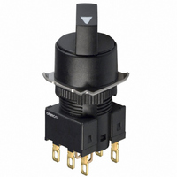
A165S-T3M-2
Description
SWITCH KNOB RND 3-POS DPDT
Manufacturer
Omron
Series
A165Sr
Type
Standardr
Specifications of A165S-T3M-2
Circuit
DPDT
Switch Function
3 Position, Maintained
Contact Rating @ Voltage
5A @ 125VAC
Illumination
Non-Illuminated
Mounting Type
Panel Mount
Termination Style
Quick Connect - .110" (2.8mm)
Panel Cutout Dimensions
16mm (Round)
Body Shape
Flange
Control Type
Knob-Type Selector
Contact Form
DPDT
Contact Rating
5 Amps at 125 VoltsAC
Flange Shape
Round
Illuminated
N
Lead Free Status / RoHS Status
Lead free / RoHS Compliant
Illumination Type, Color
-
Illumination Voltage (nominal)
-
Lead Free Status / Rohs Status
Lead free / RoHS Compliant
Other names
A165ST3M2
Z1389
Z1389


Installation
J MOUNTING
After mounting the Pushbutton Unit to the panel, snap in the
Socket Unit from the back of the panel.
Panel mounting
Insert the Pushbutton Unit into the front of the panel, and fix the
lock ring and mounting nut from the terminal side.
Make sure that the lock ring is aligned with the thread of the case
and the edge of the lock ring is touching the panel.
Tighten the mounting nuts to a torque of 0.20 to 0.39 N • m (3 to
5 kgf • cm).
The maximum tightening torque is 0.39 N • m (5 kgf • cm).
Switch Mounting
Snap on the Switch Unit to the Pushbutton Unit.
Make sure the the Switch Unit is in the proper orientation when
snapping on to the Pushbutton Unit.
J SWITCH REMOVAL
Grip the part between the Switch holder of the case and the
Switch Unit using the A16Z-5080 Extractor, and pull to remove
the Switch Unit.
Case
A16Z-5080 Extractor
Edge
Thread
Panel
Lock ring
Mounting nut
21
J REPLACEMENT PARTS
Removal and installation of the Operating Part
J REMOVING THE LAMP
Removing from the Operating Part End
Removing from the Switch Unit End
The Lamp can be removed by hand once the Switch is removed
using the A16Z-5080 Extractor.
J INSTALLING THE LAMP
When mounting the Lamp, make sure it is facing the direction
shown in the following diagram. Insert the Lamp while matching
the protruding part of the Lamp and the small guides on the outer
surface of the case.
The Lamp can be mounted from the operating part end by using
the A16Z-5080 Extractor. The lamp can be mounted by following
the opposite procedure for removing the Lamp.
Protruding part
1. Remove the operating part as shown in the following
2. To attach the operating part, push until it clicks into place.
diagram. If the operating part cannot be removed by hand,
use the A3PJ-5080 Extractor.
Lamp
Grip the Lamp with the
A16Z-5080 Extractor and
pull to remove.
Operating section
Related parts for A165S-T3M-2
Image
Part Number
Description
Manufacturer
Datasheet
Request
R

Part Number:
Description:
SWITCH KNOB SQ 2-POS SPDT
Manufacturer:
Omron
Datasheet:
Part Number:
Description:
SWITCH KNOB SQ 2-POS SPDT
Manufacturer:
Omron
Datasheet:

Part Number:
Description:
SWITCH KNOB RECT 2-POS SPDT
Manufacturer:
Omron
Datasheet:

Part Number:
Description:
SWITCH KNOB RECT 3-POS DPDT
Manufacturer:
Omron
Datasheet:

Part Number:
Description:
SWITCH KNOB RND 2-POS SPDT
Manufacturer:
Omron
Datasheet:
Part Number:
Description:
SWITCH KNOB RND 2-POS SPDT
Manufacturer:
Omron
Datasheet:

Part Number:
Description:
SWITCH KNOB SQUARE MOM 2POS DPDT
Manufacturer:
Omron
Datasheet:

Part Number:
Description:
SWITCH KNOB SQUARE ALT 2POS DPDT
Manufacturer:
Omron
Datasheet:

Part Number:
Description:
SWITCH KNOB RECT MOM 2POS DPDT
Manufacturer:
Omron
Datasheet:
Part Number:
Description:
SWITCH KNOB RECT ALT 2POS DPDT
Manufacturer:
Omron
Datasheet:

Part Number:
Description:
SWITCH PB SQUARE MOM SPDT GREEN
Manufacturer:
Omron
Datasheet:

Part Number:
Description:
SWITCH PB SQUARE MOM SPDT WHITE
Manufacturer:
Omron
Datasheet:
Part Number:
Description:
SWITCH PB SQUARE MOM SPDT YELLOW
Manufacturer:
Omron
Datasheet:
Part Number:
Description:
SWITCH PB RECTANG MOM SPDT BLUE
Manufacturer:
Omron
Datasheet:
Part Number:
Description:
SWITCH PB RECTANG MOM SPDT YEL
Manufacturer:
Omron
Datasheet: