SS-01 Omron, SS-01 Datasheet - Page 5
SS-01
Manufacturer Part Number
SS-01
Description
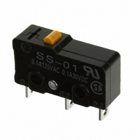
SWITCH BASIC SPDT .1A 150GF SLD
Manufacturer
Omron
Series
SSr
Type
Basic Switchesr
Specifications of SS-01
Circuit
SPDT
Switch Function
On-Mom
Contact Rating @ Voltage
0.1A @ 125VAC
Actuator Type
Round (Pin Plunger)
Mounting Type
Chassis Mount
Termination Style
Solder Lug
Operating Force
150gf
Contact Form
SPDT
Contact Rating
0.1 Amp
Actuator
Plunger, Pin
Post Position
Straight Vertical
Microswitch Type
Subminiature
Actuator Style
Pin Plunger
Operating Force Max
150gf
Contact Voltage Ac Nom
125V
Contact Voltage Dc Nom
30V
Contact Current Max
100mA
Body Style
Subminiature
Brand/series
SS-01 Series
Current, Rating
0.1 A
Dielectric Strength
1500 VAC
Force, Operating
150 g
Mounting Hole Size
2.4 mm
Number Of Poles
1
Operation
Snap Action
Standards
UL Listed, CSA Certified
Temperature Rating
-25 to +85 °C
Termination
Solder
Voltage, Rating
125/30 VAC/VDC
Lead Free Status / RoHS Status
Lead free / RoHS Compliant
Lead Free Status / RoHS Status
Lead free / RoHS Compliant, Lead free / RoHS Compliant
Other names
SS-01
SS01
SW1059
SS01
SW1059
Available stocks
Company
Part Number
Manufacturer
Quantity
Price

Part Number:
SS-01GL-E
Manufacturer:
OMRON/欧姆龙
Quantity:
20 000
Part Number:
SS-01GL13PT
Manufacturer:
OMRON/欧姆龙
Quantity:
20 000
Part Number:
SS-01GPB
Manufacturer:
OMRON/欧姆龙
Quantity:
20 000
Company:
Part Number:
SS-01GPT(GAME)
Manufacturer:
INF
Quantity:
4 306


Dimensions
■ Terminals
Note: 1. Unless otherwise specified, all units are in millimeters and a tolerance of ±0.4 mm applies to all dimensions
■ Dimensions and Operating Characteristics
Note: 1. Unless otherwise specified, all units are in millimeters and a tolerance of ±0.4 mm applies to all dimensions
Pin Plunger Models
SS-01(-E, -F)
SS-5(-F)
SS-10
Characteristics
OF max.
RF min.
PT max.
OT min.
MD max.
OP
COM
terminal
COM
terminal
(C)
Solder Terminals
PCB, Left-angled terminal
2. Terminal plate thickness is 0.5 mm for all models.
1.6
2. The following illustrations and dimensions are for solder terminal models.
3. The operating characteristics are for operation in the A direction( )
2.9
Refer to “Terminals” for models with quick-connect terminals (#110) or PCB terminals.
9.5±0.1
8.8
19.8
NO terminal
NO terminal
7.3
NC terminal
SS-01-E
3.2
NC
terminal
0.5 mm
0.5 mm
0.1 mm
25 g
2 g
6.4
6.4
OP
2.9
PT
Three,
1.6-dia. holes
6.4
2.5±0.07 dia.
2.5
2.35
COM terminal (C)
1.6
+0.075
–0.05
Note: Terminal plate thickness is 0.5 mm for all models.
COM
terminal
SS-01-F, SS-5-F
Quick-connect Terminals (#110)
5.1
2
PCB, Right-angled terminal
0.5 mm
0.1 mm
0.5 m
1.6
9.5±0.1
8.8
50 g
2.9
19.8
4 g
7.5
A
7.3
Part number
8.4 ± 0.5 mm
8.8
9.5±0.1
19.8
2.35
NO terminal
9.5
NO terminal
+0.075
–0.05
7.3
10.2
dia. holes
NC terminal
SS-01, SS-5
NC terminal
0.5 mm
0.5 mm
0.1 mm
150 g
25 g
3.2
3.2
6.4
3.2
Three, 1.2 dia.
7.1
2.8
10.6
Three, 1.6 dia.
6.4
Snap Action Switch
COM
terminal
(C)
Left-angled terminal
1.6
PCB Terminals
2.9
0.12 mm
Note: Angled terminal directions
0.6 mm
0.4 mm
SS-10
150 g
25 g
8.8
9.5±0.1
are shown below.
19.8
NO terminal
7.3
Right-angled terminal
3.3
0.5
SS
NC terminal
3.2
0.6
t = 0.5
1.2
99
7.0
Related parts for SS-01
Image
Part Number
Description
Manufacturer
Datasheet
Request
R

Part Number:
Description:
SW BASIC SPDT 10.1A 150GF SLD
Manufacturer:
Omron
Datasheet:

Part Number:
Description:
Switch, Economical, SUBMIN., Snap Action, SOLD.TERM., PIN PLUNGER, STD LOAD Actuator
Manufacturer:
Omron
Datasheet:

Part Number:
Description:
SWITCH 5A BASIC PC MNT 150GF
Manufacturer:
Omron
Datasheet:

Part Number:
Description:
SWITCH SPDT .1A SIM ROLLER SLD
Manufacturer:
Omron
Datasheet:

Part Number:
Description:
SWITCH SPDT 5A PIN PLUNGER SLD
Manufacturer:
Omron
Datasheet:

Part Number:
Description:
SWITCH SPDT 5A SIM ROLLER SLD
Manufacturer:
Omron
Datasheet:

Part Number:
Description:
SWITCH BASIC SPDT 5A
Manufacturer:
Omron
Datasheet:

Part Number:
Description:
SWITCH LEVER SPDT .1A
Manufacturer:
Omron
Datasheet:

Part Number:
Description:
SWITCH LEVER SPDT 5A
Manufacturer:
Omron
Datasheet:

Part Number:
Description:
SWITCH SIM ROLLER SPDT 5A
Manufacturer:
Omron
Datasheet:

Part Number:
Description:
SWITCH SPDT 10.1A HINGE RLLR SLD
Manufacturer:
Omron
Datasheet:

Part Number:
Description:
SUBMINIATURE BASIC SWITCH
Manufacturer:
Omron
Datasheet:

Part Number:
Description:
PIN PLUNGER SPDT 1.8OZ/5AMP
Manufacturer:
Omron
Datasheet:

Part Number:
Description:
SWITCH SPDT 5A PIN PLUNGER PCB
Manufacturer:
Omron
Datasheet:

Part Number:
Description:
SWITCH SPDT 5A HINGED ROLLER TAB
Manufacturer:
Omron
Datasheet: