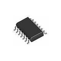
AT42QT1070-SSU Atmel, AT42QT1070-SSU Datasheet - Page 67

AT42QT1070-SSU
Manufacturer Part Number
AT42QT1070-SSU
Description
IC TOUCH SENSOR 7KEY 14-SOIC
Manufacturer
Atmel
Type
Capacitiver
Specifications of AT42QT1070-SSU
Number Of Inputs/keys
7 Key (Comms), 5 Key (Standalone)
Data Interface
I²C
Voltage Reference
Internal
Voltage - Supply
1.8 V ~ 5.5 V
Operating Temperature
-40°C ~ 85°C
Mounting Type
Surface Mount
Package / Case
14-SOIC (0.154", 3.90mm Width)
Supply Voltage
1.8 V to 5.5 V
Dimensions
3 mm L x 3 mm W x 0.8 mm H
Temperature Range
- 40 C to + 85 C
Termination Style
SMD/SMT
Lead Free Status / RoHS Status
Lead free / RoHS Compliant
Current - Supply
-
Resolution (bits)
-
Touch Panel Interface
-
Data Rate/sampling Rate (sps, Bps)
-
Lead Free Status / Rohs Status
Lead free / RoHS Compliant
Available stocks
Company
Part Number
Manufacturer
Quantity
Price
Company:
Part Number:
AT42QT1070-SSU
Manufacturer:
ATMEL
Quantity:
2 000
Company:
Part Number:
AT42QT1070-SSU QS529
Manufacturer:
Atmel
Quantity:
4 905
Touch Sensors Design Guide
Channel
Electrode
False Touch
Hand Shadow
Jitter
Key
Line
1. Sometimes called Bell-shaped or Normal distribution.
One of the capacitive measurement point at which the sensor controller can detect capacitive
change.
See also node.
The patch of conductive material on the substrate that forms the sensor. An electrode is usually (but
not always) made from copper, carbon, silver ink, Orgacon™ or Indium Tin Oxide (ITO).
An unexpected key detection caused by an interaction of the Y traces with the X traces. False
touches can occur anywhere that X and Y are too close and the field between them is allowed to be
influenced by touch. See
The situation in which a false touch is detected from the user’s hand as it is held over a sensor, rather
than from the user’s finger. This effect occurs when a sensor is particularly large in proportion to a
hand. It is a particular problem for large self-capacitance sliders and wheels. See
page
The peak-to-peak variance in the reported location for an axis when a fixed touch is applied. Typically
jitter is random in nature and has a Gaussian
jitter must be conducted over some period of time, typically a few seconds. Jitter is typically
measured as a percentage of the axis in question.
For example a 100 x 100 mm touchscreen that shows ±0.5 percent jitter in X and ±1 percent jitter in
Y would show a peak deviation from the average reported coordinate of ±0.5 mm in X and ±1 mm in
Y. Note that by defining the jitter relative to the average reported coordinate, effects of linearity are
ignored.
A simple zero-dimensional electrode arrangement whose capacitance changes when touched,
allowing touched or not-touched status (on or off) detection.
The logical X or Y line used for the detection of touches, as opposed to a physical trace.
5-2.
Section on page
4-7.
(1)
distribution, therefore measurement of peak-to-peak
Glossary of Terms
Appendix A
Section 5.2.3 on
10620D–AT42–04/09
A-1


