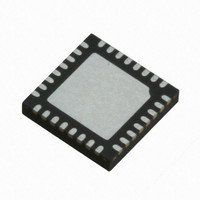
M0516ZAN Nuvoton Technology Corporation of America, M0516ZAN Datasheet - Page 159

M0516ZAN
Manufacturer Part Number
M0516ZAN
Description
IC MCU 32BIT 64KB FLASH 33QFN
Manufacturer
Nuvoton Technology Corporation of America
Series
NuMicro M051™r
Specifications of M0516ZAN
Core Processor
ARM Cortex-M0
Core Size
32-Bit
Speed
50MHz
Connectivity
EBI/EMI, I²C, IrDA, SPI, UART/USART
Peripherals
Brown-out Detect/Reset, LVD, POR, PWM, WDT
Number Of I /o
24
Program Memory Size
64KB (64K x 8)
Program Memory Type
FLASH
Ram Size
4K x 8
Voltage - Supply (vcc/vdd)
2.5 V ~ 5.5 V
Data Converters
A/D 5x12b
Oscillator Type
Internal
Operating Temperature
-40°C ~ 85°C
Package / Case
33-WFQFN Exposed Pad
Lead Free Status / RoHS Status
Lead free / RoHS Compliant
Eeprom Size
-
Available stocks
Company
Part Number
Manufacturer
Quantity
Price
Company:
Part Number:
M0516ZAN
Manufacturer:
Nuvoton
Quantity:
200
Part Number:
M0516ZAN
Manufacturer:
NUVOTON
Quantity:
20 000
- Current page: 159 of 384
- Download datasheet (4Mb)
6.5.1
6.5.2
6.5 I2C Serial Interface Controller (Master/Slave)
NuMicro M051
I2C is a two-wire, bi-directional serial bus that provides a simple and efficient method of data
exchange between devices. The I2C standard is a true multi-master bus including collision
detection and arbitration that prevents data corruption if two or more masters attempt to control
the bus simultaneously.
Data is transferred between a Master and a Slave synchronously to SCL on the SDA line on a
byte-by-byte basis. Each data byte is 8 bits long. There is one SCL clock pulse for each data bit
with the MSB being transmitted first. An acknowledge bit follows each transferred byte. Each bit is
sampled during the high period of SCL; therefore, the SDA line may be changed only during the
low period of SCL and must be held stable during the high period of SCL. A transition on the SDA
line while SCL is high is interpreted as a command (START or STOP). Please refer to the Figure
6.5-1 for more detail I2C BUS Timing.
The device’s on-chip I2C provides the serial interface that meets the I2C bus standard mode
specification. The I2C port handles byte transfers autonomously. To enable this port, the bit ENS1
in I2CON should be set to '1'. The I2C H/W interfaces to the I2C bus via two pins: SDA (Px.y,
serial data line) and SCL (Px.y, serial clock line). Pull up resistor is needed for Pin Px.y and Px.y
for I2C operation as these are open drain pins. When the I/O pins are used as I2C port, user must
set the pins function to I2C in advance.
The I2C bus uses two wires (SDA and SCL) to transfer information between devices connected to
the bus. The main features of the bus are:
SDA
SCL
Overview
Features
Support Master and Slave mode
Bidirectional data transfer between masters and slaves
Multi-master bus (no central master)
Arbitration between simultaneously transmitting masters without corruption of serial data
on the bus
STOP
t
BUF
START
t
HD;STA
™
t
LOW
Series Technical Reference Manual
Figure 6.5-1 I2C Bus Timing
t
HIGH
t
HD;DAT
- 159 -
t
r
Publication Release Date: Sept 14, 2010
t
f
t
SU;DAT
t
SU;STA
Repeated
START
Revision V1.2
t
SU;STO
STOP
Related parts for M0516ZAN
Image
Part Number
Description
Manufacturer
Datasheet
Request
R

Part Number:
Description:
Manufacturer:
Nuvoton Technology Corporation of America
Datasheet:

Part Number:
Description:
Manufacturer:
Nuvoton Technology Corporation of America
Datasheet:

Part Number:
Description:
Manufacturer:
Nuvoton Technology Corporation of America
Datasheet:

Part Number:
Description:
Manufacturer:
Nuvoton Technology Corporation of America
Datasheet:

Part Number:
Description:
Manufacturer:
Nuvoton Technology Corporation of America
Datasheet:

Part Number:
Description:
Manufacturer:
Nuvoton Technology Corporation of America
Datasheet:

Part Number:
Description:
Manufacturer:
Nuvoton Technology Corporation of America
Datasheet:


