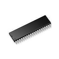
AT89LP52-20PU Atmel, AT89LP52-20PU Datasheet - Page 91

AT89LP52-20PU
Manufacturer Part Number
AT89LP52-20PU
Description
IC MCU 8051 8K FLASH SPI 40PDIP
Manufacturer
Atmel
Series
89LPr
Datasheet
1.AT89LP52-20MU.pdf
(113 pages)
Specifications of AT89LP52-20PU
Core Processor
8051
Core Size
8-Bit
Speed
20MHz
Connectivity
EBI/EMI, I²C, SPI, UART/USART
Peripherals
Brown-out Detect/Reset, POR, PWM, WDT
Number Of I /o
36
Program Memory Size
8KB (8K x 8)
Program Memory Type
FLASH
Ram Size
256 x 8
Voltage - Supply (vcc/vdd)
2.4 V ~ 5.5 V
Oscillator Type
Internal
Operating Temperature
-40°C ~ 85°C
Package / Case
40-DIP (0.600", 15.24mm)
Processor Series
AT89x
Core
8051
Data Bus Width
8 bit
Data Ram Size
256 B
Interface Type
Serial
Maximum Clock Frequency
20 MHz
Number Of Programmable I/os
36
Number Of Timers
3
Operating Supply Voltage
2.7 V to 5.5 V
Maximum Operating Temperature
+ 85 C
Mounting Style
Through Hole
Lead Free Status / RoHS Status
Lead free / RoHS Compliant
Eeprom Size
-
Data Converters
-
Lead Free Status / Rohs Status
Details
17.9.6
3709B–MICRO–12/10
Timing Parameters
The timing parameters for
and
Table 17-6.
Note:
Figure 17-15
Symbol
t
t
PWRDN
PWRUP
t
t
t
t
t
t
t
t
t
t
t
t
t
t
t
t
t
t
t
t
SHSL
SLSH
t
t
CLCL
t
t
t
t
t
AWR
POR
RHZ
SCK
t
t
SOH
SOV
POH
POV
SOE
SOX
POE
POX
SSE
SSD
ERS
RLZ
STL
ZSS
SSZ
SIH
PIH
WR
SIS
PIS
SR
SF
1. t
SCK
Programming Interface Timing Parameters
is independent of t
System Clock Cycle Time
Power On to SS High Time
Power-on Reset Time
SS Tristate to Power Off
RST Low to I/O Tristate
RST Low Settling Time
RST High to SS Tristate
Serial Clock Cycle Time
Clock High Time
Clock Low Time
Rise Time
Fall Time
Serial Input Setup Time
Serial Input Hold Time
Serial Output Hold Time
Serial Output Valid Time
Parallel Input Setup Time
Parallel Input Hold Time
Parallel Output Hold Time
Parallel Output Valid Time
Serial Output Enable Time
Serial Output Disable Time
Parallel Output Enable Time
Parallel Output Disable Time
RST Active Lead Time
RST Inactive Lag Time
SCK Setup to SS Low
SCK Hold after SS High
Write Cycle Time
Write Cycle with Auto-Erase Time
Chip Erase Cycle Time
are shown in
Parameter
Figure
Table
CLCL
17-9,
.
.
Figure
AT89LP51/52 - Preliminary
17-10,
Figure
200
t
t
t
Min
100
CLCL
SLSH
SLSH
2.5
7.5
10
75
50
10
10
10
10
25
25
0
0
5
(1)
17-11,
Figure
2 t
2 t
Max
100
60
25
25
10
35
10
35
10
25
10
25
CLCL
CLCL
1
17-12,
Figure 17-14
Units
ms
ms
ms
ns
µs
µs
µs
ns
ns
ns
ns
ns
ns
ns
ns
ns
ns
ns
ns
ns
ns
ns
ns
ns
ns
ns
ns
ns
ns
ns
ns
91


