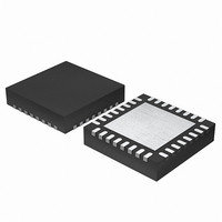
EFM32G200F64 Energy Micro, EFM32G200F64 Datasheet - Page 8

EFM32G200F64
Manufacturer Part Number
EFM32G200F64
Description
MCU 32BIT 64KB FLASH 32-QFN
Manufacturer
Energy Micro
Series
Geckor
Datasheets
1.EFM32G200F16.pdf
(63 pages)
2.EFM32G200F16.pdf
(10 pages)
3.EFM32G200F16.pdf
(463 pages)
4.EFM32G200F16.pdf
(136 pages)
Specifications of EFM32G200F64
Core Processor
ARM® Cortex-M3™
Core Size
32-Bit
Speed
32MHz
Connectivity
EBI/EMI, I²C, IrDA, SmartCard, SPI, UART/USART
Peripherals
Brown-out Detect/Reset, DMA, POR, PWM, WDT
Number Of I /o
24
Program Memory Size
64KB (64K x 8)
Program Memory Type
FLASH
Ram Size
16K x 8
Voltage - Supply (vcc/vdd)
1.8 V ~ 3.8 V
Data Converters
A/D 4x12b, D/A 1x12b
Oscillator Type
External
Operating Temperature
-40°C ~ 85°C
Package / Case
32-VQFN Exposed Pad
Processor Series
EFM32G200
Core
ARM Cortex-M3
Data Bus Width
32 bit
Data Ram Size
16 KB
Interface Type
I2C, UART
Maximum Clock Frequency
32 MHz
Number Of Programmable I/os
24
Number Of Timers
2
Operating Supply Voltage
1.8 V to 3.8 V
Maximum Operating Temperature
+ 85 C
Mounting Style
SMD/SMT
Minimum Operating Temperature
- 40 C
Lead Free Status / RoHS Status
Lead free / RoHS Compliant
Eeprom Size
-
Lead Free Status / Rohs Status
Details
Available stocks
Company
Part Number
Manufacturer
Quantity
Price
3 Electrical Characteristics
3.1 Test Conditions
3.1.1 Typical Values
3.1.2 Minimum and Maximum Values
3.2 Absolute Maximum Ratings
3.3 General Operating Conditions
3.3.1 General Operating Conditions
2010-12-17 - d0003_Rev1.20
The typical data are based on T
lation and/or technology characterisation unless otherwise specified.
The minimum and maximum values represent the worst conditions of ambient temperature, supply volt-
age and frequencies, as defined in Table 3.2 (p. 8) , by simulation and/or technology characterisa-
tion unless otherwise specified.
The absolute maximum ratings are stress ratings, and functional operation under such conditions are
not guaranteed. Stress beyond the limits specified in Table 3.1 (p. 8) may affect the device reliability
or cause permanent damage to the device. Functional operating conditions are given in Table 3.2 (p.
8) .
Table 3.1. Absolute Maximum Ratings
1
ibration values stored in flash. Please refer to the Flash section in the Electrical Characteristics for information on flash data re-
tention for different temperatures.
Table 3.2. General Operating Conditions
Based on programmed devices tested for 10000 hours at 150°C. Storage temperature affects retention of preprogrammed cal-
Symbol
T
T
V
V
Symbol
T
V
f
f
APB
AHB
STG
S
AMB
DDMAX
IOPIN
DDOP
Parameter
Storage temperature range
Maximum soldering tem-
perature
External main supply volt-
age
Voltage on any I/O pin
Parameter
Ambient temperature range
Operating supply voltage
Internal APB clock frequency
Internal AHB clock frequency
AMB
=25°C and V
Condition
Latest IPC/JEDEC J-STD-020
Standard
...the world's most energy friendly microcontrollers
8
DD
=3.0 V, as defined in Table 3.2 (p. 8) , by simu-
Min
-0.3
-40
Min
0
-40
1.8
Typ
www.energymicro.com
Typ
Max
V
Max
DD
150
+0.3 V
260 °C
3.8 V
3.8 V
85 °C
32 MHz
32 MHz
1
Unit
°C
Unit


