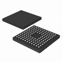
EFM32G890F64 Energy Micro, EFM32G890F64 Datasheet - Page 254

EFM32G890F64
Manufacturer Part Number
EFM32G890F64
Description
MCU 32BIT 64KB FLASH 112-BGA
Manufacturer
Energy Micro
Series
Geckor
Datasheets
1.EFM32-G890F128-SK.pdf
(70 pages)
2.EFM32-G890F128-SK.pdf
(10 pages)
3.EFM32G200F16.pdf
(463 pages)
4.EFM32G200F16.pdf
(136 pages)
Specifications of EFM32G890F64
Core Processor
ARM® Cortex-M3™
Core Size
32-Bit
Speed
32MHz
Connectivity
EBI/EMI, I²C, IrDA, SmartCard, SPI, UART/USART
Peripherals
Brown-out Detect/Reset, DMA, LCD, POR, PWM, WDT
Number Of I /o
90
Program Memory Size
64KB (64K x 8)
Program Memory Type
FLASH
Ram Size
16K x 8
Voltage - Supply (vcc/vdd)
1.8 V ~ 3.8 V
Data Converters
A/D 8x12b, D/A 2x12b
Oscillator Type
External
Operating Temperature
-40°C ~ 85°C
Package / Case
112-LFBGA
Processor Series
EFM32G890
Core
ARM Cortex-M3
Data Bus Width
32 bit
Data Ram Size
16 KB
Interface Type
I2C, UART
Maximum Clock Frequency
32 MHz
Number Of Programmable I/os
90
Number Of Timers
3
Operating Supply Voltage
1.8 V to 3.8 V
Maximum Operating Temperature
+ 85 C
Mounting Style
SMD/SMT
Minimum Operating Temperature
- 40 C
Lead Free Status / RoHS Status
Lead free / RoHS Compliant
Eeprom Size
-
Lead Free Status / Rohs Status
Details
Available stocks
Company
Part Number
Manufacturer
Quantity
Price
- EFM32-G890F128-SK PDF datasheet
- EFM32-G890F128-SK PDF datasheet #2
- EFM32G200F16 PDF datasheet #3
- EFM32G200F16 PDF datasheet #4
- Current page: 254 of 463
- Download datasheet (8Mb)
2010-09-06 - d0001_Rev1.00
complementary outputs connected to the respective low-side transistors (UL, VL, WL shown in
Figure 19.21 (p. 254) ). Transistors used in such a bridge often do not open/close instantaneously, and
using the exact complementary inputs for the high and low side of a half-bridge may result in situations
where both gates are open. This can give unnecessary current-draw and short circuit the power supply.
The DTI unit provides dead-time insertion to deal with this problem.
Figure 19.21. TIMER Triple Half-Bridge
For each of the 3 compare-match outputs of TIMER0, an additional complementary output is provided by
the DTI unit. These outputs, named TIM0_CDTI0, TIM0_CDTI1 and TIM0_CDTI2 are provided to make
control of e.g. 3-channel BLDC or PMAC motors possible using only a single timer, see Figure 19.22 (p.
254) .
Figure 19.22. TIMER Overview of Dead-Time Insertion Block for a Single PWM channel
The DTI unit is enabled by setting DTEN in TIMER0_DTCTRL. In addition to providing the
complementary outputs, the DTI unit then also overrides the compare match outputs from the timer.
The DTI unit gives the rising edges of the PWM outputs and the rising edges of the complementary
PWM outputs a configurable time delay. By doing this, the DTI unit introduces a dead-time where both
the primary and complementary outputs in a pair are inactive as seen in Figure 19.23 (p. 254) .
Figure 19.23. TIMER Polarity of Both Signals are Set as Active-High
Original PWM (TIM0_CCx_pre)
UH
UL
Original PWM
TIM0_CDTI0
TIM0_CC0
HFPERCLK
VH
VL
TIMERn
WH
WL
W
Clock control
V
U
DTFALLT
dt1
...the world's most energy friendly microcontrollers
254
Counter
Select
= 0
DTRISET
dt2
Prim ary output (TIM0_CCx)
Com plem entary Output (TIM0_CDTIx)
www.energymicro.com
Related parts for EFM32G890F64
Image
Part Number
Description
Manufacturer
Datasheet
Request
R

Part Number:
Description:
KIT STARTER EFM32 GECKO
Manufacturer:
Energy Micro
Datasheet:

Part Number:
Description:
KIT DEV EFM32 GECKO LCD SUPPORT
Manufacturer:
Energy Micro
Datasheet:

Part Number:
Description:
BOARD PROTOTYPING FOR EFM32
Manufacturer:
Energy Micro
Datasheet:

Part Number:
Description:
KIT DEVELOPMENT EFM32 GECKO
Manufacturer:
Energy Micro
Datasheet:

Part Number:
Description:
MCU, MPU & DSP Development Tools TG840 Sample Kit
Manufacturer:
Energy Micro
Datasheet:

Part Number:
Description:
MCU, MPU & DSP Development Tools TG Starter Kit
Manufacturer:
Energy Micro
Datasheet:

Part Number:
Description:
MCU, MPU & DSP Development Tools TG108 Sample Kit
Manufacturer:
Energy Micro

Part Number:
Description:
MCU, MPU & DSP Development Tools TG210 Sample Kit
Manufacturer:
Energy Micro
Datasheet:

Part Number:
Description:
MCU, MPU & DSP Development Tools TG822 Sample Kit
Manufacturer:
Energy Micro
Datasheet:

Part Number:
Description:
MCU, MPU & DSP Development Tools TG230 Sample Kit
Manufacturer:
Energy Micro

Part Number:
Description:
SAMPLE KIT (SMALL BOX - CONTAINING 2 DEVICES)
Manufacturer:
Energy Micro

Part Number:
Description:
SAMPLE KIT (SMALL BOX - CONTAINING 2 DEVICES)
Manufacturer:
Energy Micro


