KSZ8873MLLI Micrel Inc, KSZ8873MLLI Datasheet - Page 79
KSZ8873MLLI
Manufacturer Part Number
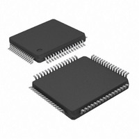
KSZ8873MLLI
Description
IC ETHERNET SWITCH 3PORT 64LQFP
Manufacturer
Micrel Inc
Specifications of KSZ8873MLLI
Controller Type
Ethernet Switch Controller
Interface
MII
Voltage - Supply
1.8V, 2.5V, 3.3V
Operating Temperature
-40°C ~ 85°C
Mounting Type
*
Package / Case
*
Number Of Primary Switch Ports
3
Internal Memory Buffer Size
32
Fiber Support
No
Integrated Led Drivers
Yes
Phy/transceiver Interface
MII
Power Supply Type
Analog
Data Rate (typ)
10/100Mbps
Vlan Support
Yes
Operating Temperature (max)
85C
Operating Temperature (min)
-40C
Mounting
Surface Mount
Jtag Support
No
Operating Supply Voltage (max)
1.89/3.465V
Operating Temperature Classification
Industrial
Data Rate
100Mbps
Lead Free Status / RoHS Status
Lead free / RoHS Compliant
Current - Supply
-
Lead Free Status / RoHS Status
Compliant, Lead free / RoHS Compliant
Available stocks
Company
Part Number
Manufacturer
Quantity
Price


Micrel, Inc.
Register 194 (0xC2): Insert SRC PVID
Register 195 (0xC3): Power Management and LED Mode
September 2009
Bit
7-6
5
4
3
2
1
0
Bit
7
6
5-4
3
2
1-0
Insert SRC
port 1 PVID at
Port 2
Insert SRC
port 1 PVID at
Port 3
Insert SRC
port 2 PVID at
Port 1
Insert SRC
port 2 PVID at
Port 3
Insert SRC
port 3 PVID at
Port 1
Insert SRC
port 3 PVID at
Port 2
CPU interface
Power Down
Switch Power
Down
LED Mode
Selection
LED output
mode
PLL Off Enable
Power
Management
Mode
Name
Reserved
Name
R/W
RO
R/W
R/W
R/W
R/W
R/W
R/W
R/W
R/W
R/W
R/W
R/W
R/W
R/W
Description
Reserved
Do not change the default value.
insert SRC port 1 PVID for untagged frame at egress port 2
insert SRC port 1 PVID for untagged frame at egress port 3
insert SRC port 2 PVID for untagged frame at egress port 1
insert SRC port 2 PVID for untagged frame at egress port 3
insert SRC port 3 PVID for untagged frame at egress port 1
insert SRC port 3 PVID for untagged frame at egress port 2
Description
CPU interface clock tree power down enable.
=1, Enable
=0, Disable
Switch clock tree power down enable.
=1, Enable
=0, Disable
=00, LED0 -> Link/ACT, LED1-> Speed
=01, LED0 -> Link,
=10, LED0 -> Link/ACT, LED1 -> Duplex
=11, LED0 -> Link,
=1, The internal stretched energy signal from the analog
module will be negated and output to LED1 and the internal
device ready signal will be negated and output to LED0.
=0, The LED1/LED0 pins will indicate the regular LED
outputs.
(Note. This is for debugging purpose.)
=1, PLL power down enable
=0, Disable
Power management mode
=00, Normal Mode
=01, Energy Detection Mode
=10, Software Power Down Mode
=11, Power Saving Mode
LED1 -> ACT
LED1 -> Duplex
79
Default
00
0
0
0
0
0
0
Default
0
0
00
0
0
00
KSZ8873MLL/FLL/RLL
M9999-092309-1.2
Related parts for KSZ8873MLLI
Image
Part Number
Description
Manufacturer
Datasheet
Request
R

Part Number:
Description:
Manufacturer:
Micrel Inc
Datasheet:
Part Number:
Description:
Manufacturer:
Micrel Inc
Datasheet:
Part Number:
Description:
Manufacturer:
Micrel Inc
Datasheet:
Part Number:
Description:
Manufacturer:
Micrel Inc
Datasheet:
Part Number:
Description:
Manufacturer:
Micrel Inc
Datasheet:
Part Number:
Description:
Manufacturer:
Micrel Inc
Datasheet:
Part Number:
Description:
Manufacturer:
Micrel Inc
Datasheet:
Part Number:
Description:
Manufacturer:
Micrel Inc
Datasheet:
Part Number:
Description:
Manufacturer:
Micrel Inc
Datasheet:
Part Number:
Description:
Manufacturer:
Micrel Inc
Datasheet:
Part Number:
Description:
Manufacturer:
Micrel Inc
Datasheet:
Part Number:
Description:
Manufacturer:
Micrel Inc
Datasheet:
Part Number:
Description:
Manufacturer:
Micrel Inc
Datasheet:
Part Number:
Description:
Manufacturer:
Micrel Inc
Datasheet: