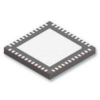
DS92LV2421SQE/NOPB National Semiconductor, DS92LV2421SQE/NOPB Datasheet - Page 3

DS92LV2421SQE/NOPB
Manufacturer Part Number
DS92LV2421SQE/NOPB
Description
IC SER/DESER 10-75MHZ 24B 48LLP
Manufacturer
National Semiconductor
Datasheet
1.DS92LV2421SQENOPB.pdf
(40 pages)
Specifications of DS92LV2421SQE/NOPB
Serdes Function
Serialiser
Ic Input Type
LVCMOS
Ic Output Type
CML
No. Of Inputs
1
No. Of Outputs
1
Supply Voltage Range
1.71V To 1.89V
Driver Case Style
LLP
No. Of Pins
48
Svhc
No SVHC
Rohs Compliant
Yes
Lead Free Status / RoHS Status
Lead free / RoHS Compliant
Other names
DS92LV2421SQE/NOPBTR
Available stocks
Company
Part Number
Manufacturer
Quantity
Price
Company:
Part Number:
DS92LV2421SQE/NOPB
Manufacturer:
NSC
Quantity:
1 250
Part Number:
DS92LV2421SQE/NOPB
Manufacturer:
TI/德州仪器
Quantity:
20 000
Pin Name
LVCMOS Parallel Interface
DI[7:0]
DI[15:8]
DI[23:16]
CI1
CI2
CI3
DS92LV2421 Pin Diagram
DS92LV2421 Serializer Pin Descriptions
34, 33, 32, 29,
42, 41, 40, 39,
28, 27, 26, 25
38, 37, 36, 35
46, 45, 44, 43
2, 1, 48, 47,
Pin #
5
3
4
w/ pull-down
w/ pull-down
w/ pull-down
w/ pull-down
w/ pull-down
w/ pull-down
I, LVCMOS
I, LVCMOS
I, LVCMOS
I, LVCMOS
I, LVCMOS
I, LVCMOS
I/O, Type
Description
Parallel Interface Data Input Pins
For 8–bit RED Display: DI7 = R7 – MSB, DI0 = R0 – LSB.
Parallel Interface Data Input Pins
For 8–bit GREEN Display: DI15 = G7 – MSB, DI8 = G0 – LSB.
Parallel Interface Data Input Pins
For 8–bit BLUE Display: DI23 = B7 – MSB, DI16 = B0 – LSB.
Control Signal Input
For Display/Video Application: CI1 = Data Enable Input
Control signal pulse width must be 3 clocks or longer to be transmitted when the Control
Signal Filter is enabled (CONFIG[1:0] = 01). There is no restriction on the minimum
transition pulse when the Control Signal Filter is disabled (CONFIG[1:0] = 00). The signal
is limited to 2 transitions per 130 clocks regardless of the Control Signal Filter setting.
Control Signal Input
For Display/Video Application: CI2 = Horizontal Sync Input
Control signal pulse width must be 3 clocks or longer to be transmitted when the Control
Signal Filter is enabled (CONFIG[1:0] = 01). There is no restriction on the minimum
transition pulse when the Control Signal Filter is disabled (CONFIG[1:0] = 00). The signal
is limited to 2 transitions per 130 clocks regardless of the Control Signal Filter setting.
Control Signal Input
For Display/Video Application: CI3 = Vertical Sync Input
CI3 is limited to 1 transition per 130 clock cycles. Thus, the minimum pulse width allowed
is 130 clock cycle wide.
Serializer - DS92LV2421 — Top View
3
30110119
www.national.com


