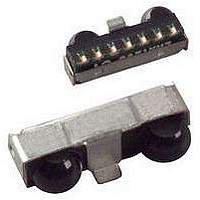
TFDU4101-TR3 Vishay, TFDU4101-TR3 Datasheet - Page 8

TFDU4101-TR3
Manufacturer Part Number
TFDU4101-TR3
Description
Infrared Transceivers SIR 115.2 kbits/s
Manufacturer
Vishay
Type
Serialr
Specifications of TFDU4101-TR3
Data Transmission Rate
2.4 Kbits/s to 115.2 Kbits/s
Input Current
10 mA
Mounting Style
SMD/SMT
Power Dissipation
250 mW
Wavelength
900 nm
Continual Data Transmission
115.2 Kbit/s
Transmission Distance
1 m
Radiant Intensity
65 mW/sr
Half Intensity Angle Degrees
24 deg
Pulse Width
2.2 us
Maximum Rise Time
100 ns, 300 ns
Maximum Fall Time
100 ns, 300 ns
Operating Voltage
2.4 V to 5.5 V
Maximum Operating Temperature
+ 85 C
Minimum Operating Temperature
- 30 C
Dimensions
9.7 mm x 4.7 mm x 4 mm
Data Rate Max
115.2Kbps
Data Transmission Distance
1m
Peak Wavelength
900nm
Supply Current
90µA
Supply Voltage Range
2.4V To 5.5V
Operating Temperature Range
-30°C To +85°C
Msl
MSL 4 - 72 Hours
Package
8Ultra Small Profile
Maximum Data Rate
0.1152 Mbps
Operating Supply Voltage
2.4 to 5.5 V
Operating Temperature Max
85°C
Rohs Compliant
Yes
Current I Led Dc
80mA
Data Rate
115.2kbs (SIR)
Idle Current, Typ @ 25° C
75µA
Link Range, Low Power
1m
Operating Temperature
-30°C ~ 85°C
Orientation
Side View
Shutdown
*
Size
9.7mm x 4.7mm x 4mm
Standards
IrPHY 1.0
Supply Voltage
2.4 V ~ 5.5 V
Svhc
No SVHC (20-Jun-2011)
Lead Free Status / RoHS Status
Lead free / RoHS Compliant
Lead Free Status / RoHS Status
Lead free / RoHS Compliant, Lead free / RoHS Compliant
Available stocks
Company
Part Number
Manufacturer
Quantity
Price
Company:
Part Number:
TFDU4101-TR3
Manufacturer:
TI
Quantity:
1 001
Company:
Part Number:
TFDU4101-TR3
Manufacturer:
vishay21
Quantity:
90
Part Number:
TFDU4101-TR3
Manufacturer:
VISHAY/威世
Quantity:
20 000
TFDU4101
Vishay Semiconductors
Figure 2 shows an example of a typical application
with a separate supply voltage V
transceiver with the IRED Anode connected to the
unregulated battery V
peak load of the regulated power supply and saves
therefore costs. Alternatively all supplies can also be
tied to only one voltage source. R1 and C1 are not
used in this case and are depending on the circuit
design in most cases not necessary.
In figure 2 an option is shown to operate the
transmitter at two different power levels to switch for
long range to low power mode for e.g. saving power
for IrDA application but use the full range specification
for remote control. The additional components are
marked in the figure.
For operating at RS232 ports TOIM4232 is
recommended as ENDEC.
Table 2.
Truth table
www.vishay.com
8
V batt
Hi/Low
V s = 2.8 V
20038
> 1 ms
high
≈
SD
low
3 V
Grey: Optional for Hi/Low Switching.
Figure 2. Typical Application Circuit.
IR MODE
V
dd
IRRX
IRTX
high < 50 µs
high > 50 µs
TXD
low
low
low
x
batt
. This method reduces the
Inputs
R2
C2
Optical input Irradiance mW/m
R1
< Max. irradiance E
> Max. irradiance E
> Min. irradiance E
S
IRED Anode (1)
IRED Cathode (2)
TXD (3)
RXD (4)
SD (5)
Vcc1 (6)
GND (8)
and using the
C1
< 4
x
x
x
e
e
e
2
I/
In the description, already different I/Os are
mentioned. Different combinations are tested and the
function verified with the special drivers available
from the I/O suppliers. In special cases refer to the
I/O manual, the Vishay application notes, or contact
directly Vishay Sales, Marketing or Application.
Current Derating Diagram
Figure 3 shows the maximum operating temperature
when the device is operated without external current
limiting resistor.
(500 kΩ) to V
O and Software
weakly pulled
high inactive
high inactive
low (active)
low active
undefined
18097
RXD
90
85
80
75
70
65
60
55
50
2.0
Outputs
CC1
Figure 3. Current Derating Diagram
2.5
Operating Voltage (V) at duty cycle 20 %
Transmitter
3.0
I
0
0
0
0
0
e
3.5
4.0
Shutdown
Transmitting
Protection is active
Ignoring low signals below
the IrDA defined threshold for
noise immunity
Response to an IrDA
compliant optical input signal
Overload conditions can
cause unexpected outputs
Document Number 81288
4.5
Rev. 1.2, 04-Dec-07
Operation
Remark
5.0
5.5
6.0


