ASMT-JY32-NTVH1 Avago Technologies US Inc., ASMT-JY32-NTVH1 Datasheet
ASMT-JY32-NTVH1
Specifications of ASMT-JY32-NTVH1


Related parts for ASMT-JY32-NTVH1


ASMT-JY32-NTVH1 Summary of contents
Page 1
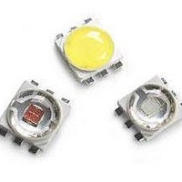
... ASMT-Jx32 3W Mini Power LED Light Source Data Sheet Description The 3W Mini Power LED Light Source is a high perfor- mance energy efficient device which can handle high thermal and high driving current. The metal slug is electri- cally isolated. The White Mini Power LED is available in the range of color temperature from 2700K to 10000K ...
Page 2
... Package Dimensions 5.0 4.0 Metal Slug 0.65 Figure 1. ASMT-Jx32 package outline drawing 2 0.8 NC Anode Lead NC Body 0.60 Notes: 1. All dimensions in millimeters. 2. Tolerance is ±0.1 mm unless otherwise specified. Ø 1.70 3. Terminal finish: Ag plating. 4. Corresponding NC (No Connection) leads adjacent to anode and cathode leads can be electrically short. ...
Page 3
... Part Numbering System ASMT – Note: 1. Please refer to Page 8 for selection details. Device Selection Guide (T = 25°C) J Part Number Color ASMT-JW32-NUV01 Cool White ASMT-JW32-NVV01 ASMT-JN32-NUV01 Neutral White ASMT-JN32-NVV01 ASMT-JY32-NTV01 Warm White Notes the total luminous flux output as measured with an integrating sphere at 25ms mono pulse condition. ...
Page 4
... Min. InGaN 2.8 Note Thermal Resistance from LED junction to metal slug. J-MS Optical and Electrical Characteristic at 700 mA (T Part Number Color ASMT-JW32-NUV01 Cool White ASMT-JW32-NVV01 ASMT-JN32-NUV01 Neutral White ASMT-JN32-NVV01 ASMT-JY32-NTV01 Warm White 4 Correlated Color Temperature, CCT (Kelvin) Min. Max. 4500 10000 ...
Page 5
WAVELENGTH - nm Figure 2. Relative Intensity vs. Wavelength for Cool White and Warm White 2 1.8 1.6 1.4 1.2 1 0.8 0.6 0.4 ...
Page 6
ANGULAR DISPLACEMENT - DEGREES Figure 8. Radiation Pattern for Cool White, Warm White and Neutral White 120.0 110.0 100.0 90.0 80.0 70.0 60.0 50.0 40.0 ...
Page 7
Solder Pad Slug Indepdent 1.32 Solder Pad Figure 13. Recommended soldering land pattern 255 - 260°C 3°C/SEC. MAX. 217°C 200°C 150°C 3°C/SEC. MAX 120 SEC. TIME Figure 15. Recommended Reflow Soldering Profile Note: For detail information on ...
Page 8
... Option Selection Details ASMT – – Minimum Flux Bin Selection 3 x – Maximum Flux Bin Selection 4 x – Color Bin Selection 5 x – Packaging Option 6 Color Bin Selection [ Individual reel will contain parts from one color bin selection only. Cool White ...
Page 9
VM 6300K 0. 7000K 0. 0.32 WP 10000K 0.30 YA 0.28 0.26 0.26 0.28 0.30 0.32 0.34 X-COORDINATE Figure 16. Color bin Structure ...
Page 10
Color Bin Limits Cool Color Limits White (Chromaticity Coordinates) Bin UM x 0.365 0.367 y 0.386 0.400 Bin UN x 0.365 0.362 y 0.386 0.372 Bin U0 x 0.362 0.360 y 0.372 0.357 Bin UP x 0.360 0.357 y 0.357 ...
Page 11
... Tolerance: ±0.01 11 Packaging Option [x Selection 0.397 0.402 1 0.406 0.423 0.392 0.397 0.391 0.406 0.402 0.409 Example 0.382 0.400 ASMT-JW32-NUV01 0.396 0.402 0.367 0.382 ASMT-JW32-Nxxxx – Cool White, InGaN, 0.382 0.386 0.397 0.413 0.378 0.382 0.382 0.397 0.374 0.378 0.366 0.382 ...
Page 12
Tape and Reel – Option 1 4.00 ±.10 8.00 ±.10 8° 4.15 ±.10 Figure 19. Carrier Tape Dimensions 3 ±0.5 ø10 178 ±1 4 ±0.5 Notes: 1. Empty component pockets sealed with top cover tape. 2. 250 or 500 pieces ...
Page 13
USER FEED DIRECTION PRINTED LABEL Figure 21. Reeling Orientation DISCLAIMER: Avago’s products and software are not specifically designed, manufactured or authorized for sale as parts, components or assemblies for the planning, construction, maintenance or direct operation of a nuclear facility ...