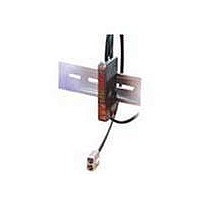
E3X-CN11 Omron, E3X-CN11 Datasheet - Page 19

E3X-CN11
Manufacturer Part Number
E3X-CN11
Description
Industrial Photoelectric Sensors Master Connector
Manufacturer
Omron
Specifications of E3X-CN11
Light Source
Red LED
Connection
Master Connector
Lead Free Status / RoHS Status
Lead free / RoHS Compliant
■
(AND)
(sync)
OUT
OUT
(OR)
OUT
CH1
CH2
E3X-MDA@
OFF
OFF
OFF
OFF
OFF
Operation Indicator
for Channel 1
(orange)
ON when output is ON.
OFF when output is OFF.
ON
ON
ON
ON
ON
Lock Button
Locks the fiber.
No incident light
T
Main Display (Red)
Incident level,
function, etc.
Incident light
D-ON
L-ON
OFF delay
ON delay
OFF
OFF
One-shot
ON
ON
(AND)
(AND)
(AND)
CH1
CH2
Operation Indicator
for Channel 2
(orange)
ON when output is ON.
OFF when output is OFF.
OFF
OFF
OFF
OFF
OFF
T
ON
ON
ON
ON
ON
CH1/
CH2
Operation
indicator (orange)
Output
transistor
Load (relay)
CH1/
CH2
Operation
indicator (orange)
Output
transistor
Load (relay)
Sub-Display (Green)
Threshold, function
settings, etc.
T
T
No incident light
No incident light
T
T
Incident light
Incident light
Release
Release
Operate
Operate
Mode Selector
Use to select SET or RUN mode.
OFF
OFF
OFF
OFF
ON
ON
ON
ON
Channel Selector
(Between blue
and black)
(Between blue
and black)
Operation Keys
Function setting operations
UP
DOWN
MODE
No incident light
Incident light
D-ON
L-ON
OFF
OFF
ON
ON
T
Display
T
Operation indicator
(orange)
ch 1
Photo-
electric
Sensor
main
circuit
Operation indicator
(orange) ch 2
No incident light
Incident light
D-ON
L-ON
OFF
OFF
ON
ON
Orange
Brown
Black
Blue
Control
output 2
Control
output 1
T
Load
T
Load
12 to
24 VDC


