EE-SPY402 Omron, EE-SPY402 Datasheet - Page 7
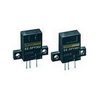
EE-SPY402
Manufacturer Part Number
EE-SPY402
Description
Photomicrosensors 5MM LIGHT-ON REFLECT
Manufacturer
Omron
Series
-r
Specifications of EE-SPY402
Output Configuration
Light-On
Sensing Distance
5 mm
Sensing Method
Diffuse
Termination Style
Through Hole
Input Current Max
50mA
Optocoupler Output Type
Transistor
Output Voltage
1V
Input Current
15mA
No. Of Pins
3
Opto Case Style
Module
No. Of Channels
1
Svhc
No SVHC (15-Dec-2010)
Frequency Response Max
100Hz
Sensing Range Max
5mm
Sensor Input
Optical
Supply Voltage Dc Max
24V
Connector Type
DEDICATED 3 OR 4
External Depth
7mm
Output Type
Light - On
Operating Temperature Range
-10°C To +55°C
Operating Voltage Max
24VDC
Operating Voltage Min
5VDC
Rohs Compliant
Yes
External Length / Height
20mm
External Width
26mm
Fixing Centres
20mm
Load Current Max
80mA
Sensing Object
White Paper
Sensing Light
Infrared
Mounting Type
Through Hole
Current - Supply
15mA
Voltage - Supply
5 V ~ 24 V
Package / Case
PCB Mount
Features
Supports Connection With PLCs
Lead Free Status / RoHS Status
Lead free / RoHS Compliant
Lead Free Status / RoHS Status
Lead free / RoHS Compliant
Other names
OMREESPY402
Available stocks
Company
Part Number
Manufacturer
Quantity
Price
Company:

Part Number:
EE-SPY402
Manufacturer:
Omron Electronics
Quantity:
135
Company:
Part Number:
EE-SPY402
Manufacturer:
OMRON
Quantity:
1 000


Precautions
Refer to the Technical Information Section for general
precautions.
J WIRING
A cable with a thickness of 0.3 mm
of 2 m max. must be connected to the output terminals.
To use a cable longer than 2 m, attach a capacitor with a
capacitance of approximately 10 µF to the wires, as shown
below. The distance between the terminal and the capacitor must
be within 2 m:
Do not solder the cable to the connectors. Use the EE-1002
Connector or EE-1003 Connector (with a 1-m cable attached) to
connect the cable to the output terminals.
Use the EE1003A Connector Holder to prevent accidental
disconnection of the EE-1003 Connector from the
EE-SPY301/401/302/402 Photomicrosensor.
Do not impose excessive force on the terminals (refer to the
diagram below). Excess force will damage the terminals.
Do not disconnect the EE-1001 or EE-1006 Connector from the
photomicrosensor when power is supplied to the
photomicrosensor, or sensor damage could result.
If the metal mounting base is subjected to inductive electrical
noise, the photomicrosensor can be activated accidentally. If
noise is a problem, take the following countermeasures:
1. Connect the negative terminal to the mounting base so that
2. Connect the negative terminal to the mounting base via a
Cat. No. GC APMS-1
No
1-800-55-OMRON
OMRON ELECTRONICS LLC
One East Commerce Drive
Schaumburg, IL 60173
there will be no difference in electric potential between the
photomicrosensor and mounting base.
0.47-µF capacitor.
OUT
NOTE: DIMENSIONS SHOWN ARE IN MILLIMETERS. To convert millimeters to inches divide by 25.4.
A capacitance of
10 µF min.
5 to 24 VDC
2 m max
0 V
R
09/02
2
Terminal
or AWG22 min. and a length
Extension
cable
OMRON ON- -LINE
Global -- http://www.omron.com
USA -- http://www.omron.com/oei
Canada -- http://www.omron.com/oci
Specifications subject to change without notice.
3. Insert a plastic insulating plate with a thickness of approxi-
Wire as shown by the following illustration to connect a small
inductive load (a relay for example) to the photomicrosensor. A
diode must be connected parallel to the relay to absorb the
reverse voltage.
When using a standard switching regulator, ground the FG and G
terminal to ensure that the photomicrosensor will be in a stable
operating condition.
J POWER SUPPLY
When using a standard switching regulator, ground the FG and G
terminal to ensure that the photomicrosensor will be in a stable
operating condition.
mately 10 mm between the photomicrosensor and mounting
base.
OUT
OUT
D
Relay
OMRON CANADA, INC.
Toronto, Ontario M1B 5V8
416-286-6465
885 Milner Avenue
Switching
regulator
G
FG
0 V
5 to 24 VDC
Printed in U.S.A.
Related parts for EE-SPY402
Image
Part Number
Description
Manufacturer
Datasheet
Request
R

Part Number:
Description:
Photomicrosensors 13mm P Modulated SLOT PMS L-On
Manufacturer:
Omron
Datasheet:

Part Number:
Description:
Photomicrosensors PMOD 5mmSD D-ON SS
Manufacturer:
Omron
Datasheet:
Part Number:
Description:
Photomicrosensors DIFFUSE PMS PMOD 5mm
Manufacturer:
Omron
Datasheet:

Part Number:
Description:
Photomicrosensors CONV REFL DARK-ON
Manufacturer:
Omron
Datasheet:

Part Number:
Description:
Photomicrosensors REFL PHOTO IC
Manufacturer:
Omron
Datasheet:
Part Number:
Description:
Photomicrosensors CONV REFL LIGHT-ON
Manufacturer:
Omron
Datasheet:

Part Number:
Description:
Photomicrosensors REFL LIGHT-ON/DRK-ON
Manufacturer:
Omron
Datasheet:
Part Number:
Description:
Photomicrosensors CONV REFL LIGHT-ON
Manufacturer:
Omron
Datasheet:
Part Number:
Description:
Photomicrosensors REFL LIGHT-ON/DRK-ON
Manufacturer:
Omron
Datasheet:

Part Number:
Description:
Photomicrosensors REFL LIGHT-ON
Manufacturer:
Omron
Datasheet:


Part Number:
Description:
PHOTO MICROSENSOR
Manufacturer:
Omron
Datasheet:

Part Number:
Description:
PHOTO MICROSENSOR :
Manufacturer:
Omron
Datasheet:

Part Number:
Description:
PHOTO MICROSENSOR
Manufacturer:
Omron
Datasheet:

Part Number:
Description:
PHOTO MICROSENSOR
Manufacturer:
Omron
Datasheet: